Image processing device and ultrasonic diagnostic device

Inactive Publication Date: 2005-02-01
KONICA MINOLTA INC
View PDF8 Cites 18 Cited by
  • Summary
  • Abstract
  • Description
  • Claims
  • Application Information

AI Technical Summary

Benefits of technology

In view of the foregoing, it is the first object of the present invention to provide an image processing device or an ultrasonic diagnostic device that makes an examination using a synchronization signal possible without inputting a synchroniz

Problems solved by technology

However, in the case of the conventional ultrasonic diagnostic device, since the above-mentioned synchronization signal is inputted into the ultrasonic diagnostic device through the special-purpose electrode for ECG 54, the ultrasonic diagnostic device needs a special-purpose circuit and a special-purpose cable, and therefore the cost for diagnosis becomes high, and at the same time space to set up an external device is necessary.
In addition, for use in the clinical medicine field, sin

Method used


Image

  • Image processing device and ultrasonic diagnostic device
  • Image processing device and ultrasonic diagnostic device
  • Image processing device and ultrasonic diagnostic device

Examples


first embodiment

(The First Embodiment)

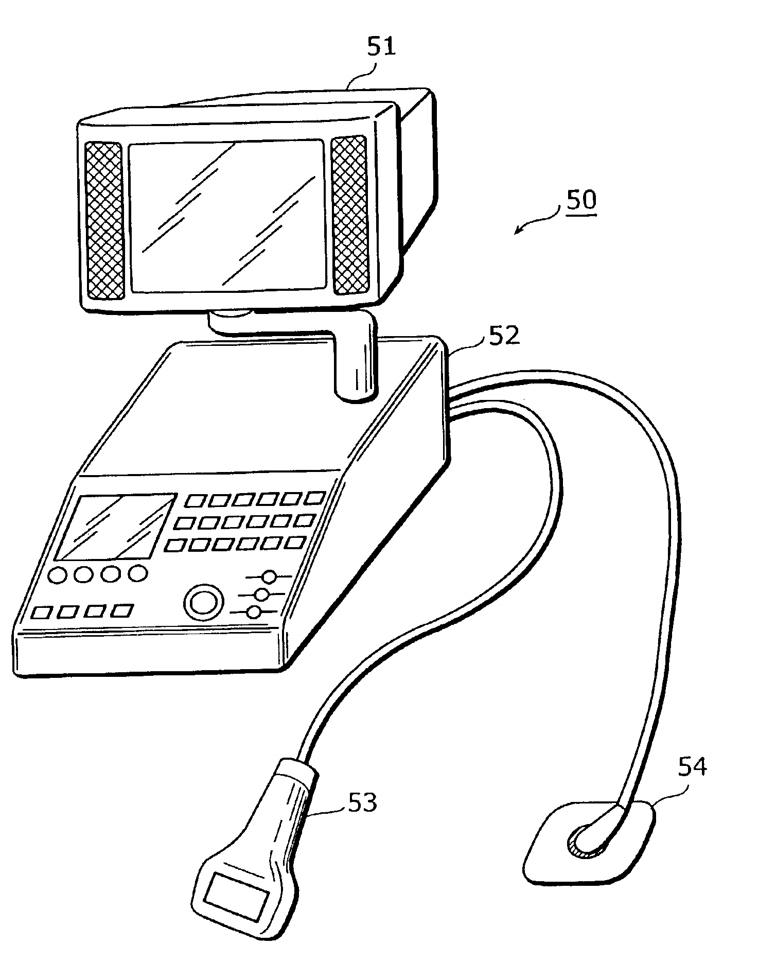
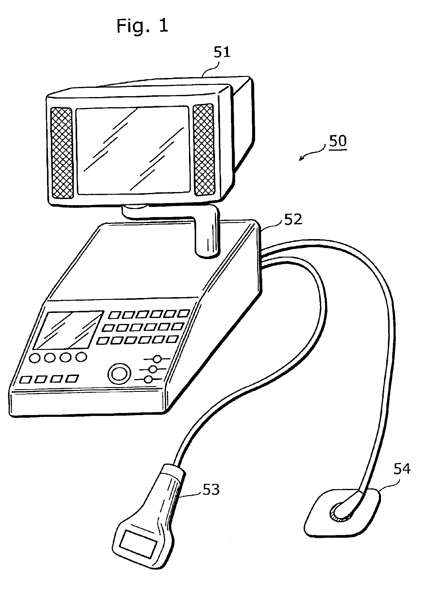
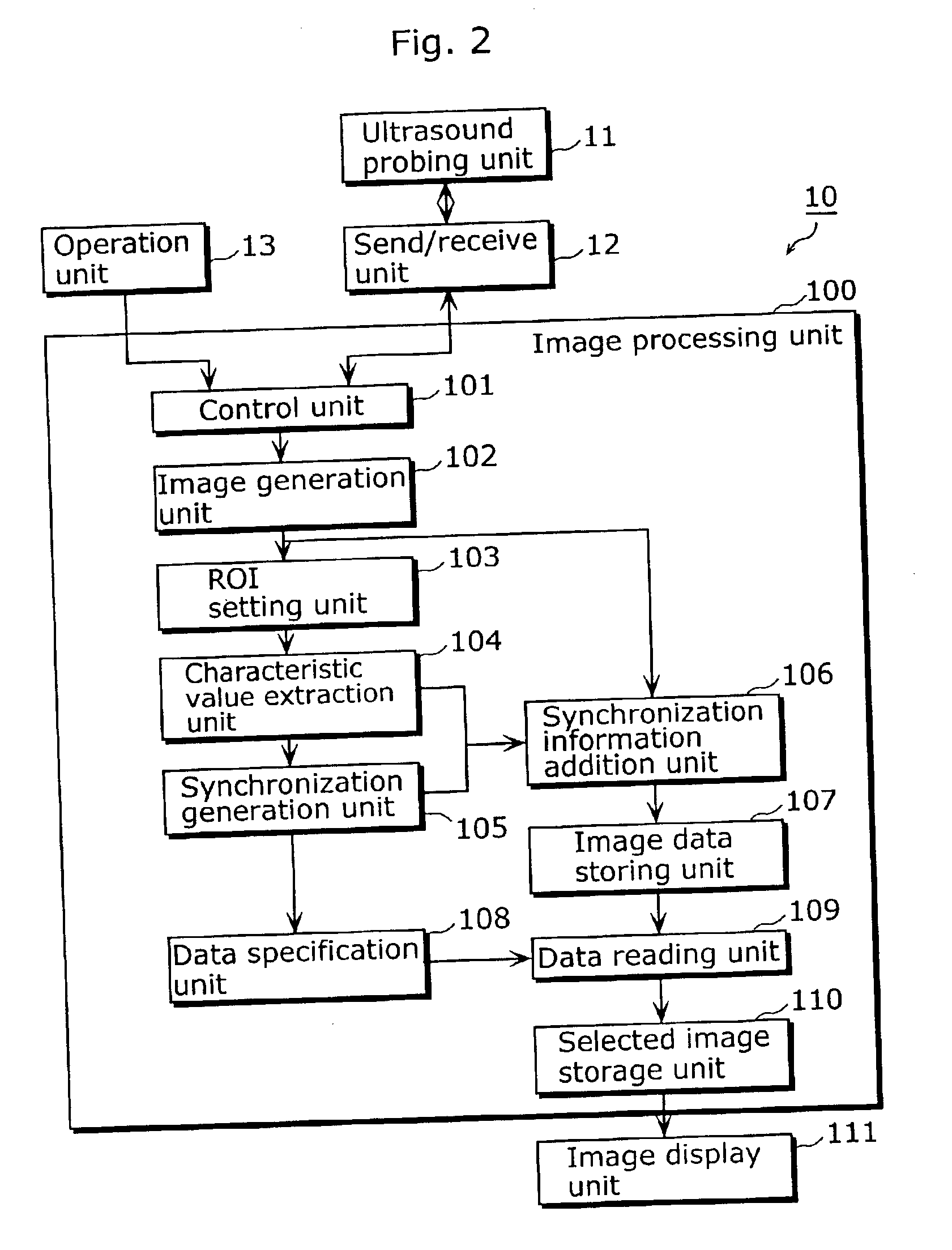
FIG. 2 is a block diagram that shows a functional configuration of an ultrasonic diagnostic device 10 according to the first embodiment. The present device 10 is an ultrasonic diagnostic device that has a function that generates a synchronization signal from an acquired tomographic image and includes an ultrasonic search unit 11, a send / receive unit 12, an operation unit 13, an image processing unit 100 and an image display unit 111.

The ultrasonic search unit 11 is generally called a probe and is, for example, a probe that performs an electronic scan based on a phased array method. The ultrasonic search unit 11 emits ultrasound (e.g., ultrasonic pulse) based on a control signal received from the send / receive unit 12. Further, the search unit 11 also receives ultrasound (hereafter called “ultrasonic echo”) reflected from inside the living body of the test object (hereafter, also called “patient”), converts the ultrasonic echo into an electric signal, and sends t...

second embodiment

(The Second Embodiment)

FIG. 8 is a block diagram that shows the functional configuration of an ultrasonic diagnostic device 20 according to the second embodiment. While the ultrasonic diagnostic device 10 according to the first embodiment stores the tomographic image to which the synchronization information is added temporarily in the image data storage unit 107 and displays the synchronous tomographic image, the present device 20 displays the synchronous tomographic image more rapidly without storing the tomographic image to which the synchronization information is added temporarily. In the following description, the configuration different from the first embodiment is explained in detail, while the common configuration is given the same numbers and the explanation thereof is omitted.

The ultrasonic diagnostic device 20 differs from the ultrasonic diagnostic device 10 in that the device 20 includes an image data selection unit 202 in place of the image data storage unit 107 and the ...

third embodiment

(The Third Embodiment)

FIG. 11 is a block diagram that shows the functional configuration of an ultrasonic diagnostic device 30 according to the third embodiment. The present ultrasonic diagnostic device 30 executes a reduced display and a scroll display of the tomographic image and a warning notification when an abnormality about the characteristic value occurs. Further, the present device 30 displays the extracted characteristic value, the generated synchronization signal and the tomographic image at the same time in one screen.

Note that in the following description, similar to the second embodiment, the configuration different from the first and second embodiments is explained in detail, while the common configuration is given the same numbers and the explanation thereof is omitted.

The ultrasonic diagnostic device 30 differs from the ultrasonic diagnostic device 10 in that the device 30 includes a characteristic value storage unit 302, a characteristic value reading unit 303, a sy...


PUM


Abstract

An image generation unit generates image data of a tomographic image based on an electric signal received from a send/receive unit through a control unit. An ROI setting unit sets an ROI to the generated tomographic image. A characteristic value extraction unit extracts a characteristic value (such as volume of left ventricular of a heart) to the set ROI. A synchronization generation unit generates a synchronization signal based on the extracted characteristic value. A synchronization information addition unit adds information that represents the generated synchronization signal to image data and stores the image data in an image data storage unit. A data reading unit reads out the image data to which the information that represents the synchronization signal is added from the image data storage unit. An image display unit displays a tomographic image of the read-out image data.

Description

BACKGROUND OF THE INVENTION(1) Field of the InventionThe present invention relates to image display devices such as an ultrasonic diagnostic device and a CT (Computerized Tomography) device, and particularly to an image processing technology for a tomographic image obtained by irradiating an examined object with ultrasound, X rays and the like.(2) Description of the Prior ArtAn image display device irradiates an anatomy (a test subject) with a diagnostic signal. (hereafter called “signal”) such as ultrasound and X rays, receives a signal reflected from the anatomy or a signal passing through the anatomy and executes imaging of the inside of the anatomy based on the received signal. In recent years, such an image display device has been widely used in industry and clinical medicine fields. Representative examples of such devices are an ultrasonic diagnostic device using a reflected signal and a CT device using a signal that passes through.These image display devices can measure the a...

Claims


Application Information

Patent Timeline
IPC IPC(8): A61B8/00G06T11/00G06T7/20A61B6/00G01R33/32A61B5/055A61B6/03A61B8/02A61B8/08
CPCG06T7/20A61B8/00A61B6/541Y10S128/916
Inventor OMIYA, JUN
Owner KONICA MINOLTA INC
Why Eureka
Try Eureka