Thin film magnetic tape head and method of manufacturing therefor

a technology of magnetic tape and head, which is applied in the field of thin film magnetic tape head, can solve the problems of increasing the complexity of assembly process, increasing the effective separation distance between the tape and the head, and reducing the stability of the combination structure, so as to improve the structural stability and improve the structural stability

Inactive Publication Date: 2005-02-01
LAFE
View PDF15 Cites 0 Cited by
  • Summary
  • Abstract
  • Description
  • Claims
  • Application Information

AI Technical Summary

Benefits of technology

Another object of the present invention is to provide a structurally sound magnetic recording head with simplified manufacturing processes and material control.
One or more ridges are formed in a top surface of the combination of the U-bar, the I-block, and the cluster. This top surface is parallel to a plane defined by the longitudinal direction in which the back portion of the U-bar extends and by the lateral direction in which the leg portions of the U-bar extend. Each of these ridges provides a tape bearing surface of the magnetic tape head. One of these tape bearing surfaces may include a portion of the cluster for interfacing with a tape, and for improved structural stability this tape bearing surface may also include a portion of the I-block.
The combination of the U-bar, the I-block, and the cluster may be fixed to a base member preferably made of ceramic or metal, such as aluminum, to further improve structural stability.
According to still another aspect of the present invention, a method of manufacturing a magnetic tape head is provided including a step of providing a frame bar having a back portion extending in a longitudinal direction and a plurality of spaced-apart leg portions extending from the back portion of the frame bar in a lateral direction. The method also includes a step of fixing at least one ceramic block, called an I-block, to the frame bar such that the I-block partially fills a space between two respective ones of the plurality of leg portions of the frame bar. The method further includes a step of fixing a cluster to the frame bar such that at least a portion of the cluster partially fills the space between two respective ones of the plurality of leg portions of the frame bar. In addition, the I-block and the cluster are arranged such that the I-block is interposed between the cluster and the back portion of the frame bar. In accordance with this method, one or more magnetic tape heads may be assembled from a single frame bar. This may be accomplished by including a step of cutting the frame bar into at least two pieces, at least one of the two pieces including a portion of the frame bar, the at least one I-block, and the at least one cluster. Also, this method includes a step of forming at least one ridge in a surface which includes a portion of the top surface of the frame bar as described above. The step of forming at least one ridge may be performed before the step of cutting the frame bar to facilitate forming ridges in one or more magnetic tape heads at once.
Finally, the above methods may include a step of fixing the combination of the U-bar, the I-block, and the cluster to a base member preferably made of ceramic or metal, such as aluminum, to further improve structural stability. Also, one or more of the steps of providing an I-block bar, which is an uncut plurality of I-blocks, and providing a cluster bar, which is an uncut plurality of clusters, cutting the I-block bar into at least two pieces, and cutting the cluster bar into at least two pieces. In addition, a step of fixing the I-block bar to the cluster bar may be performed before the steps of cutting the I-block bar and cutting the cluster bar, so that the I-block bar and the cluster bar are cut in a single operation.

Problems solved by technology

The multitude of components in the prior art designs increases the complexity in the assembly processes.
The stability of a head structure built with many building blocks also lowers the stability of the combination structure.
Any minute shift of one component relative to the others can produce a tiny step on the tape bearing surface, which may result in an increase in the effective separation distance between the tape and head.
Conventional head structures have the common problem of too many components and involve a relatively large amount of adhesive bonding to form the structure.
The multitude of components adhered together can render the magnetic head structurally unstable.
During service life, individual portions of the combination head can shift relative to each other due to aging of the adhesive and other stresses, forming detrimental stepped tape bearing surfaces.

Method used


Image

  • Thin film magnetic tape head and method of manufacturing therefor
  • Thin film magnetic tape head and method of manufacturing therefor
  • Thin film magnetic tape head and method of manufacturing therefor

Examples


first embodiment

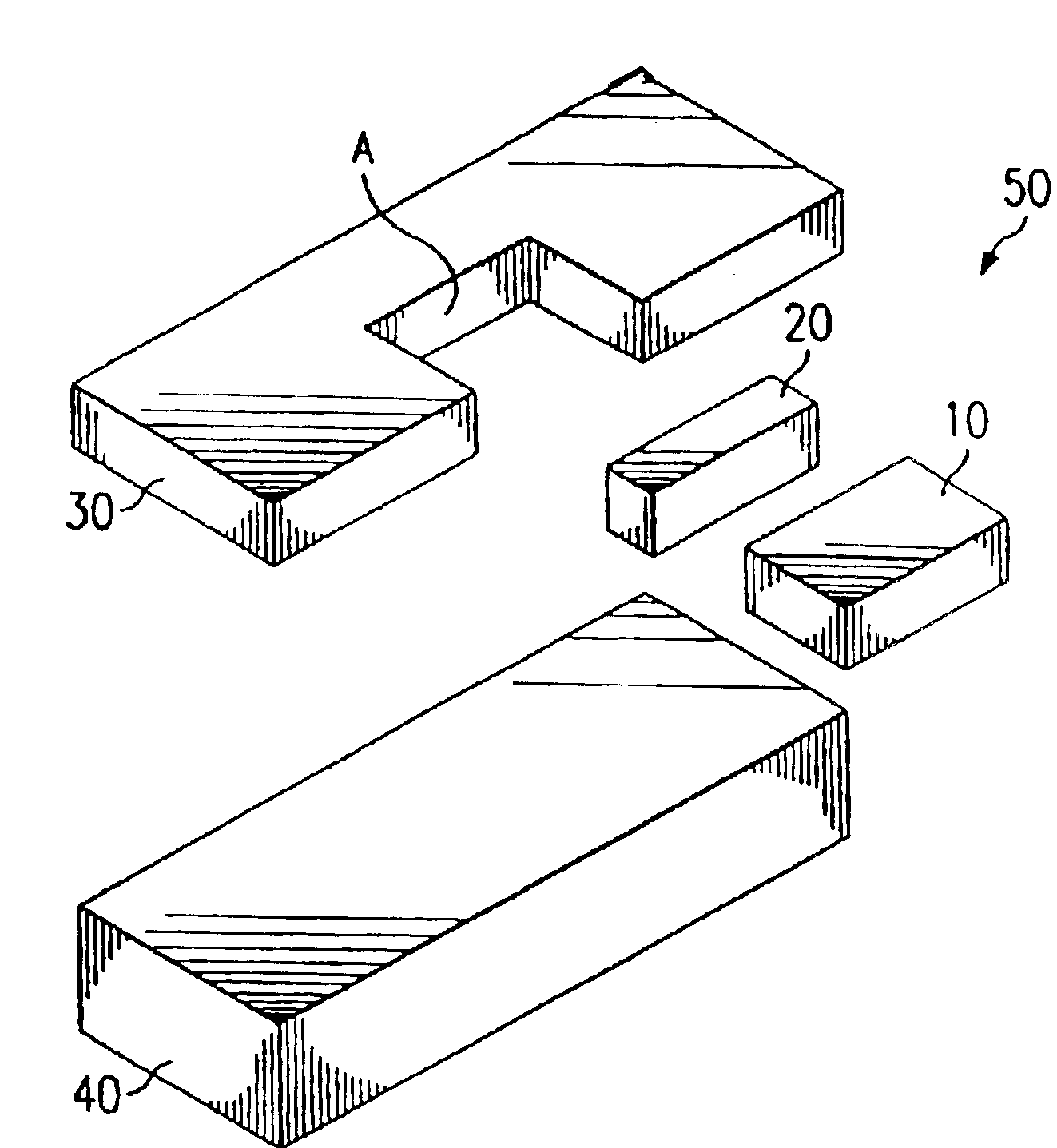
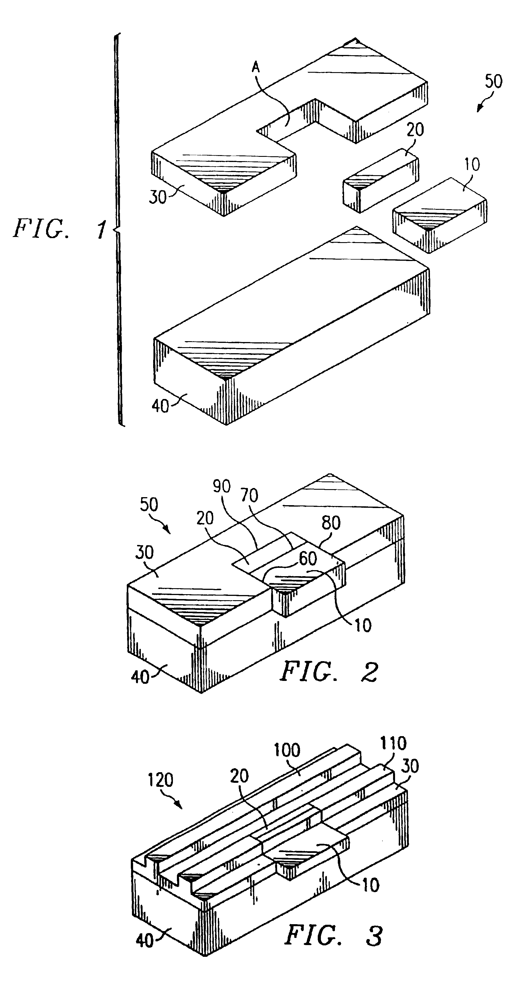
FIG. 3 shows a final magnetic head assembly 120 in accordance with the present invention. This final assembly 120 includes tape bearing surfaces 100 and 110, which are narrow ridges formed by machining or etching adjacent portions of a top portion of the slider 50. Once formed, it is preferable to profile and highly-polish the tape bearing surfaces 100 and 110 to allow for a smooth, low friction contact for a magnetic tape to pass over.

As mentioned above, the I-block 20 serves to simplify the manufacturing of the magnetic recording head of the present invention. It is preferable to have a controlled bond lines surrounding the cluster 10. However, it is difficult to achieve a desired level of precision on the surface A (shown in FIG. 1) of the U-bar 30 in order to adequately achieve the controlled bond line at the device surface of the cluster 10. However, by interposing the I-block 20 between the cluster 10 and the surface A, the I-block 20 can compliment a geometrical mismatch betw...

second embodiment

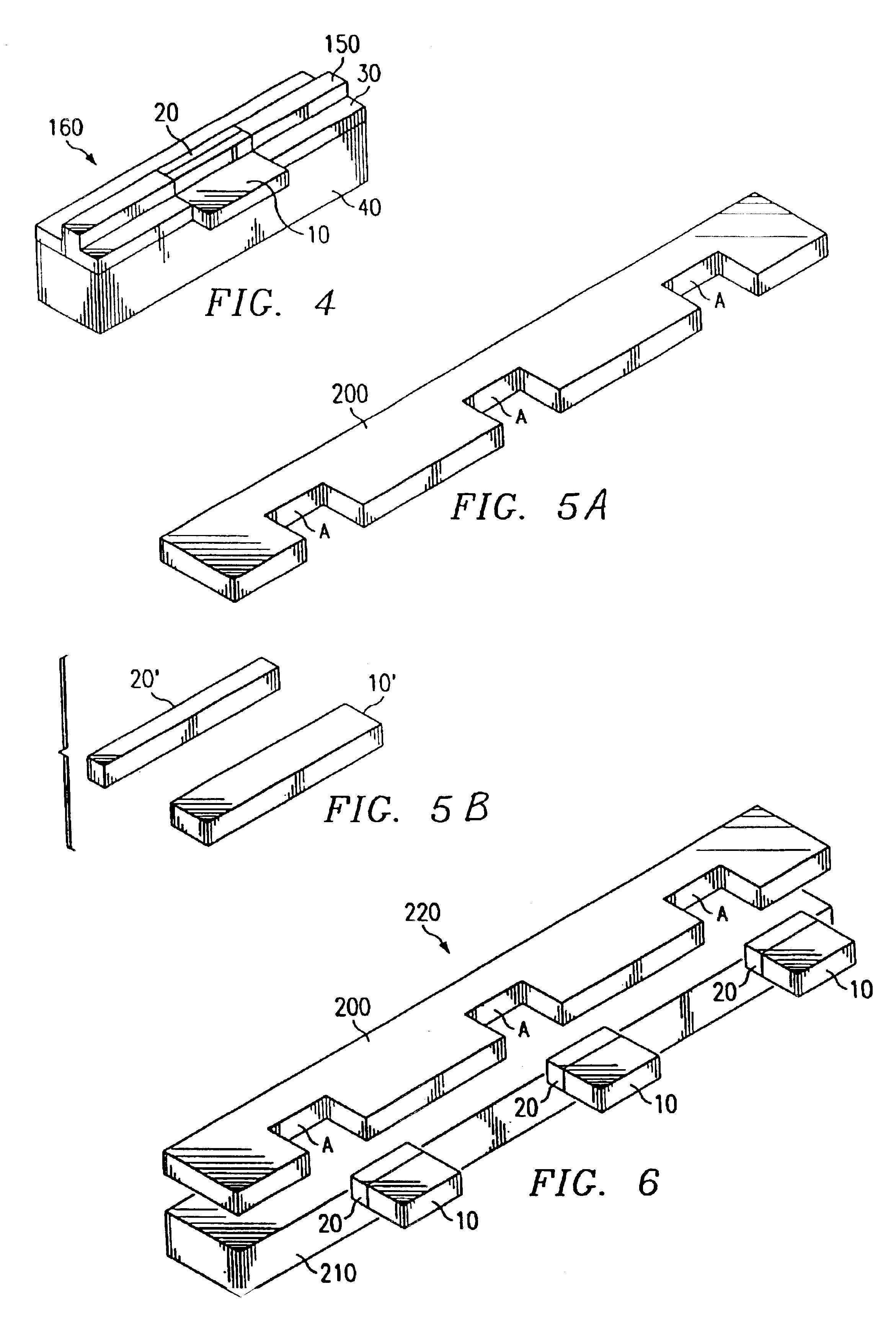
While this method is illustrated in FIGS. 5-9 by way of an example in which three magnetic heads are assembled at once, one skilled in the art would appreciate that this method is not restricted to three, but may be adapted to manufacture any number of magnetic heads at once. In addition, this method may be easily adapted to assemble heads in accordance with the second embodiment, wherein only a single tape bearing surface is formed. Finally, the descriptions above are not intended to restrict in any way the order in which the frame bar 200, each I-block 20, each cluster 10, and the base bar 210 must be assembled.

The above-described method may also be modified such that portions of the slider bar 220 are cut off before forming tape bearing surfaces thereon. Such a modification may be desirable, for example, if magnetic heads having differing numbers of tape bearing surfaces are desired.


PUM

PropertyMeasurementUnit
speedaaaaaaaaaa
pressureaaaaaaaaaa
stabilityaaaaaaaaaa

Abstract

A magnetic tape head assembly is provided along with a method of manufacturing a magnetic tape head. The magnetic tape head comprises a cluster of thin film inductive or magnetoresistive read / write elements, an I-block preferably made of a ceramic material, a U-bar also preferably made of a ceramic material, and a base preferably made of a ceramic or metal material. The U-bar has a substantially U-shaped form providing a recess into which the I-block and the cluster are fixed. A bottom surface of the U-bar, I-block, and cluster is fixed to the base to form a slider assembly. A top surface of the U-bar, I-block, and cluster is machined or etched to form one or more tape bearing surfaces thereon.

Description

FIELD OF THE INVENTIONThe invention relates to a thin-film magnetic head for use in magnetic tape recording. Further, the invention relates to a method of producing such a thin-film magnetic tape head.DESCRIPTION OF THE RELATED ARTEver growing demands for high performance and low cost magnetic recording for application in tape backup systems urge the need for improved product design and related manufacturing processes.For the special features of linear longitudinal tape head design, conventional head structures heretofore typically consist of four to five separate components to form a slider on which a tape bearing surface is built. These components are glued together with high performance adhesive to form a rigid, non-moving body to service the high-speed, high-pressure and highly abrasive tape contact for its read and write function.The multitude of components in the prior art designs increases the complexity in the assembly processes. The stability of a head structure built with ...

Claims


Application Information

Patent Timeline
Patent Type & Authority Patents(United States)
IPC IPC(8): G11B5/49
CPCG11B5/4938Y10T156/10Y10T29/49055Y10T29/49044Y10T29/49048Y10T156/1082Y10T29/49059Y10T156/1052Y10T29/49052Y10T29/49043Y10T29/49046Y10T29/49032
Inventor LAM, CHUCK FAI
Owner LAFE
Why Eureka
Try Eureka