Linear motor

a linear motor and motor body technology, applied in the field of linear motors, can solve the problems of difficult cooling of the member requires an installation space, and the movable coil assembly 103 generates considerable hea

Inactive Publication Date: 2005-02-01
CHRONOFANG
View PDF15 Cites 30 Cited by
  • Summary
  • Abstract
  • Description
  • Claims
  • Application Information

AI Technical Summary

Problems solved by technology

Such a linear motor poses the problems discussed below.
Furthermore, the flexible cable supporting member requires an installation space.
Second, the movable coil assembly 103 generates considerable heat, whereas it is difficult to cool the movable coil assembly 103 since it moves.
In addition, a large space for cooling and a complicated cooling structure would be necessary.
This causes the workpieces being carried, such as semiconductor wafers, mounted on the table to devel

Method used


Image

  • Linear motor
  • Linear motor
  • Linear motor

Examples


Embodiment Construction

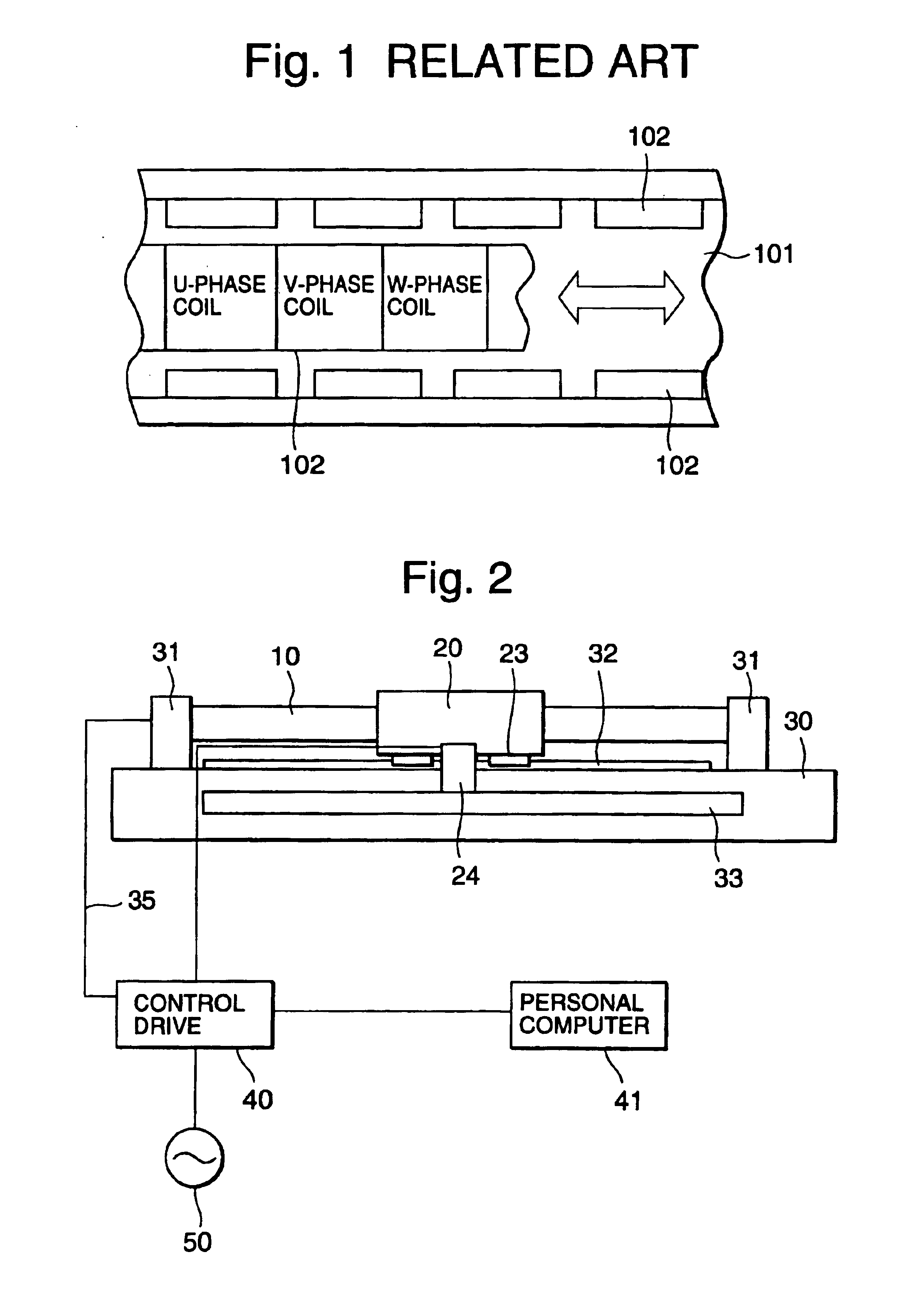
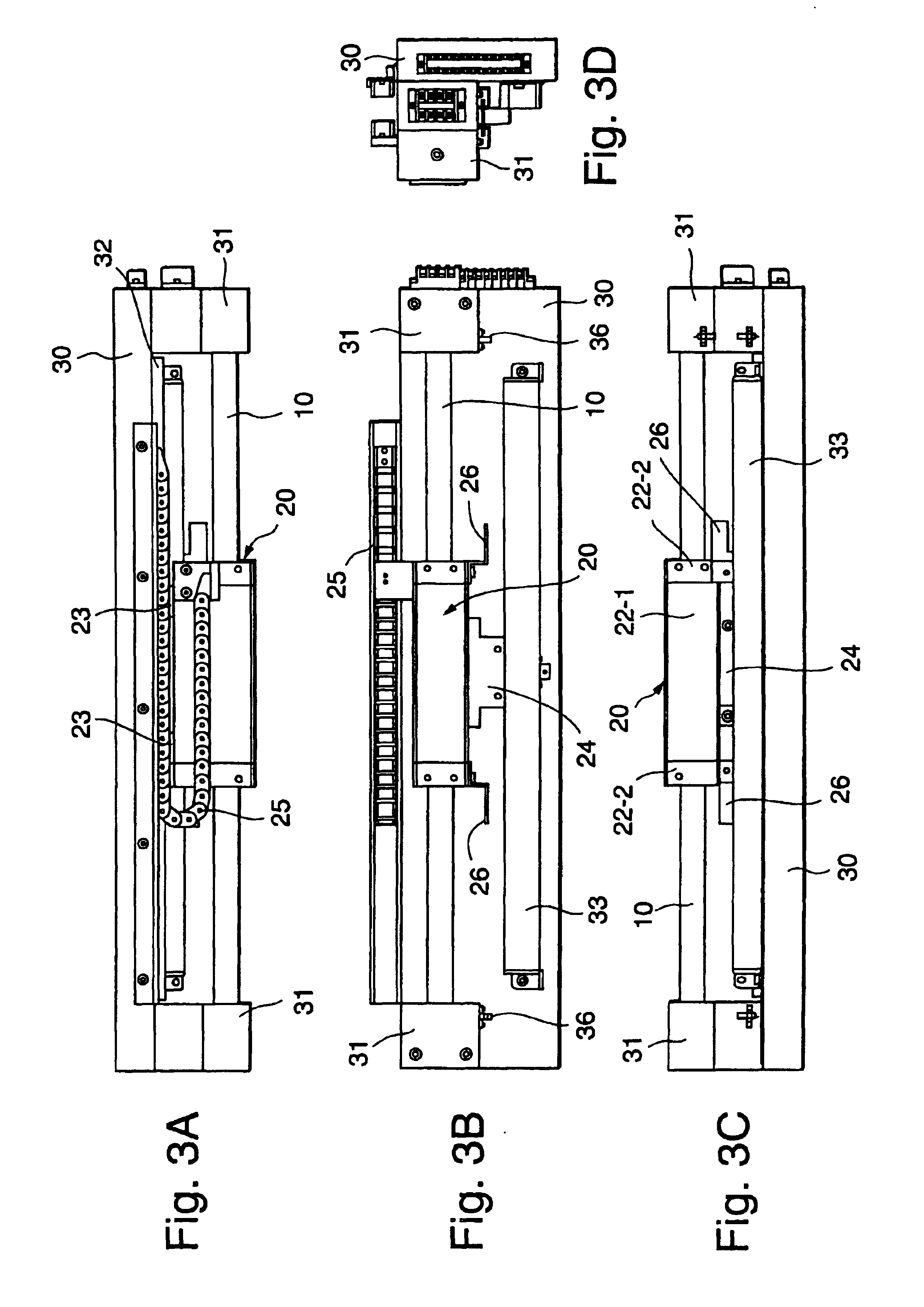
FIG. 2 shows a schematic construction of a linear motor according to a first embodiment of the present invention, and FIG. 3A through FIG. 3D are the views of a linear motor 4 shown in FIG. 2 and observed from four directions. More specifically, FIG. 3B is a top plan view, FIG. 3C is a side view observed from the lower side in FIG. 3B, FIG. 3A is a side view observed from the upper side in FIG. 3B, and FIG. 3D is a view observed from the right in FIG. 3B.

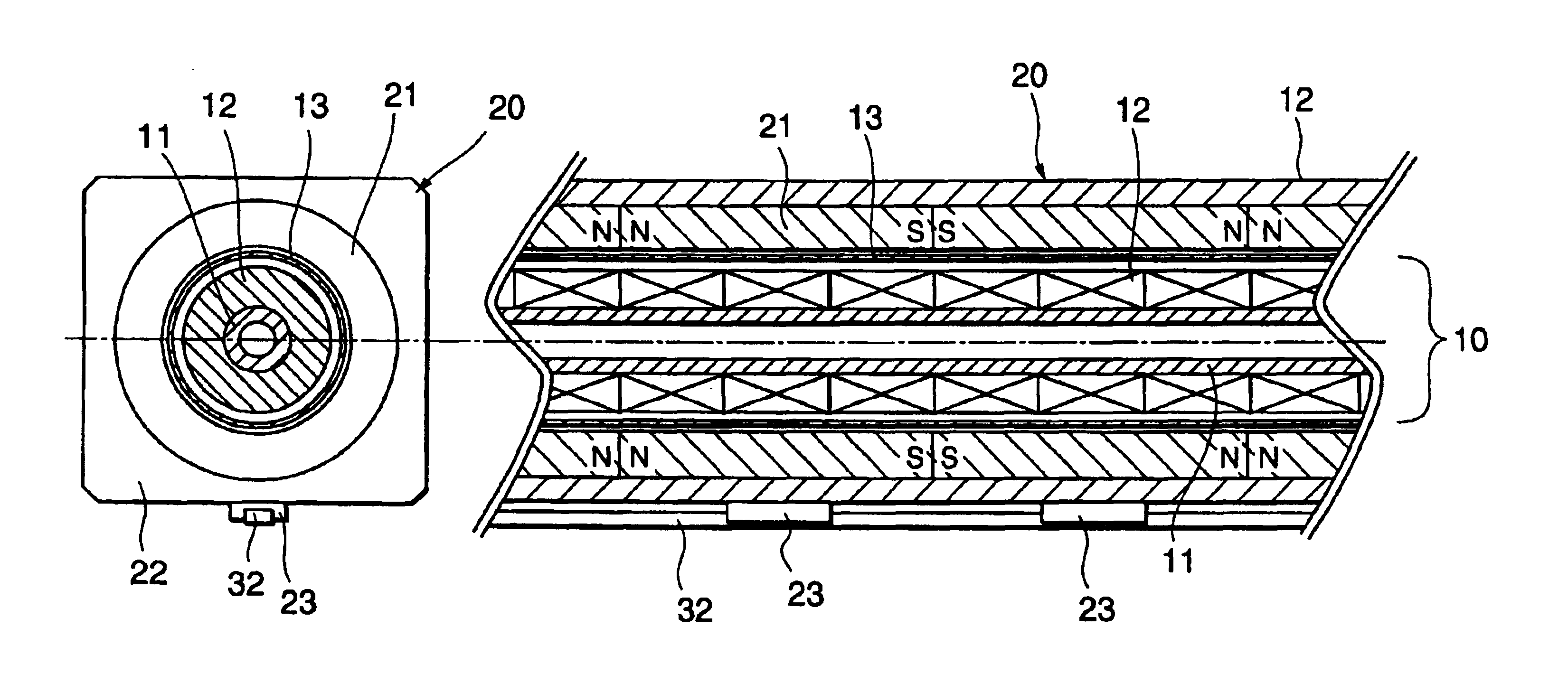
Referring to FIG. 2 and FIGS. 3A through 3D, the linear motor includes a shaft assembly (hereinafter referred to as “the stator”) 10 that houses a plurality of electromagnetic coils (hereinafter referred to as “the coils”) continuously arranged such that they are in close contact with each other. The linear motor also includes a movable magnet assembly (hereinafter referred to as “the mover”) 20 that can travel in the same direction as that in which the stator 10 extends by the interaction between itself and the magnetic fluxes from...


PUM


Abstract

A linear motor includes a plurality of electromagnetic coils continuously arranged and a magnet assembly disposed such that it may travel due to the interaction between itself and the magnetic fluxes from the coils. The coils include U, V, and W phase coils in star connection. The coils of the individual phases are installed in series around a hollow-shaft center core over the travel range of the magnet assembly such that the magnetic pole axis thereof is oriented in the same direction as the axis of the center core. The magnet assembly has an annular shape so that it may surround the coils, and is formed of a plurality of permanent magnets. The magnets are combined in series such that the same magnetic poles oppose each other and the magnetic pole axis is oriented in the same direction as the axis of the center core.

Description

BACKGROUND OF THE INVENTIONThe present invention relates to a linear motor.A variety of types of linear motors are available. Most linear motors that are not required to provide high driving power as in the case of the driving source for a linear motorcar are implemented by combining permanent magnets and electromagnetic coils. A linear motor combining permanent magnets and electromagnetic coils is considered to be applicable to a driving source for a precision micro stage or a precision positioning stage in the field of, for example, semiconductor manufacturing equipment. This is because a driving mechanism based on a linear motor is advantageous in that it provides a higher driving speed and higher positioning accuracy than those provided by a ball screw driving mechanism, which has conventionally been mainstream. The driving mechanism using a linear motor is also advantageous in that it has high repetitious positioning accuracy, has less overshoot and undershoot at starts and sto...

Claims


Application Information

Patent Timeline
IPC IPC(8): H02K41/03
CPCH02K41/03
Inventor WATANABE, KOJI
Owner CHRONOFANG
Why Eureka
Try Eureka