Catalyst deterioration detecting system for an automobile

a technology of deterioration detection and catalyst, which is applied in the direction of fire alarms, electrical control, instruments, etc., can solve the problems of insufficient purification of exhaust gas, and increased thermal load of downstream catalyst on the downstream side. to achieve the effect of accurately detecting the degree of deterioration of upstream catalys

Inactive Publication Date: 2005-02-01
HONDA MOTOR CO LTD
View PDF13 Cites 17 Cited by
  • Summary
  • Abstract
  • Description
  • Claims
  • Application Information

AI Technical Summary

Benefits of technology

In a further aspect of the invention, the activation detector of the catalyst deterioration detecting system is configured to determine activation of each catalyst based on respective temperatures of the upstream and downstream catalysts. The catalyst deterioration detecting system can accurately determine activation of catalysts based on the temperature of each catalyst.
According to this aspect of the invention, the catalyst deterioration detecting system can determine a status where only the upstream catalyst is working as a catalyst, so that the system can avoid the influence from the downstream catalyst and can accurately detect the degree of deterioration of the upstream catalyst.

Problems solved by technology

Therefore, purification of the exhaust gas is not sufficiently performed immediately after the engine start.
However, thermal load of the downstream catalyst on the downstream side occasionally increases depending on the operational conditions, so that deterioration of the downstream catalyst on the downstream side may progress more quickly than the upstream catalyst.
This structure incurs extra cost due to increase of the number of the sensors and has a drawback that the control scheme becomes complicated.

Method used


Image

  • Catalyst deterioration detecting system for an automobile
  • Catalyst deterioration detecting system for an automobile
  • Catalyst deterioration detecting system for an automobile

Examples


Embodiment Construction

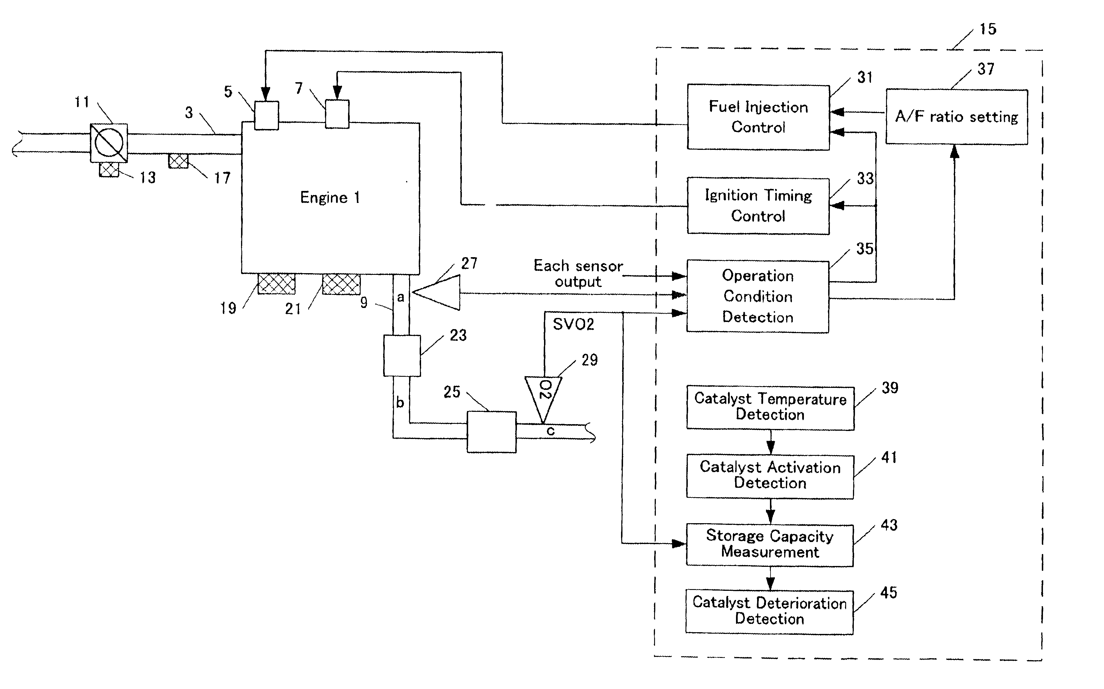
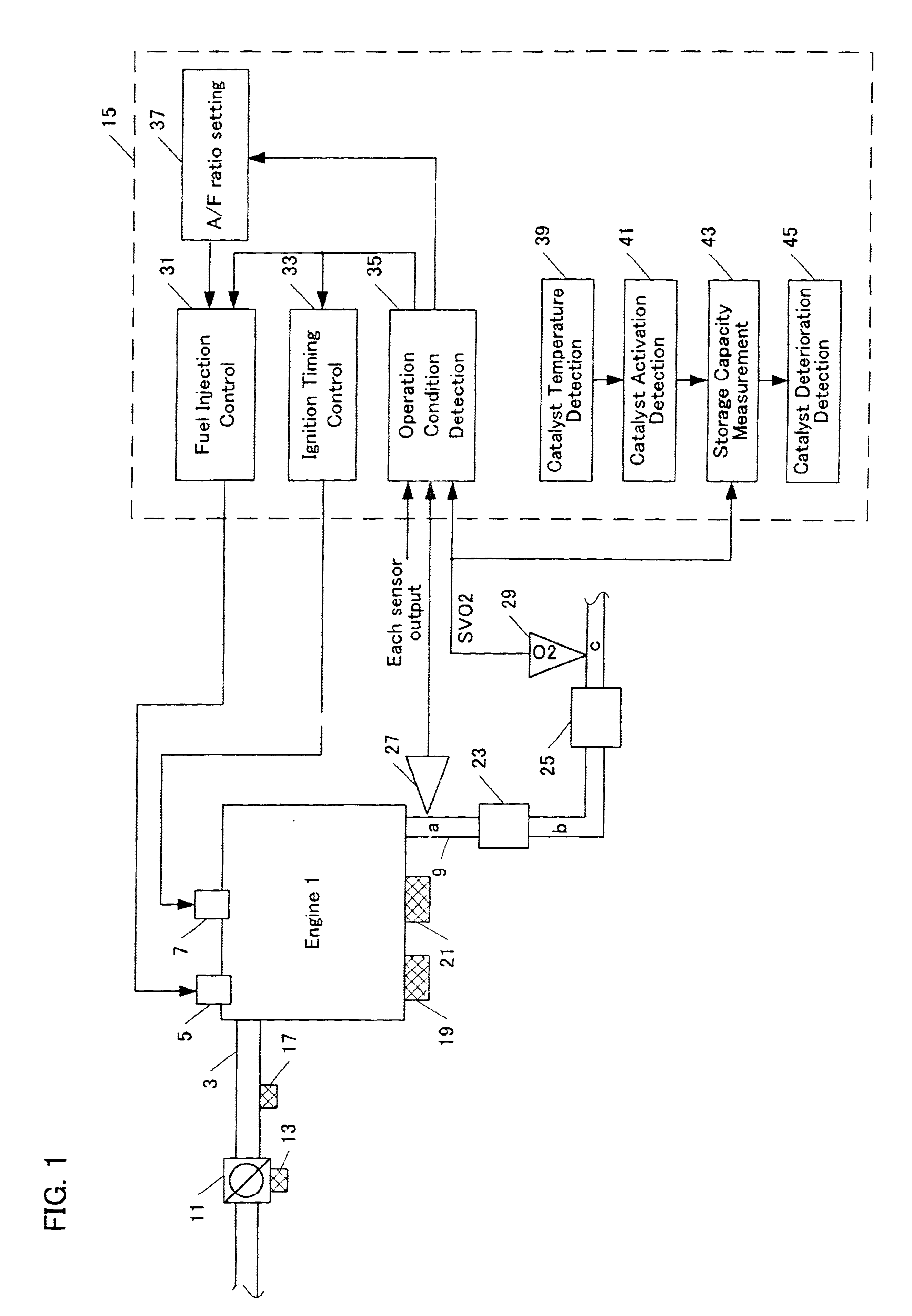
Referring to the accompanying drawings, a preferred embodiment of the invention will be described. FIG. 1 illustrates a block diagram of the engine 1 and a control unit for the engine 1. The engine 1 includes an intake duct or manifold 3, a fuel injector 5, a spark plug 7 and an exhaust pipe 9.

The intake manifold 3 is provided with a throttle valve 11 connected to a throttle valve open degree (θ TH) sensor 13. The sensor 13 outputs an electric signal corresponding to the open degree of the throttle valve 11 and provides its output to an electronic control unit (will be referred to as “ECU” hereinafter) 15. Furthermore, the intake manifold 3 is provided with an intake manifold internal pressure sensor 17 for detecting the pressure inside the intake manifold.

The engine 1 is provided with an engine revolution speed (Ne) sensor 21 for detecting the revolution speed of the engine 1. This sensor provides an output pulse to ECU every time crankshaft of the engine 1 rotates 180 degrees. Thi...


PUM


Abstract

The invention provides a catalyst deterioration detecting system that is capable of detecting the degree of deterioration of each catalyst in a catalyst converter which includes two or more catalysts in series.The catalyst deterioration detecting system of an internal-combustion engine according to the invention is provided with a upstream catalyst located on an upstream side of an exhaust system of the internal-combustion engine and a downstream catalyst located on a downstream side of the exhaust system. The device comprises an oxygen density detector which is disposed downstream of the downstream catalyst and a deterioration detector for detecting a deterioration degree of the upstream catalyst based on the output of the oxygen density detector. According to an aspect of the invention, the deterioration detector detects deterioration degree of the downstream catalyst based on the previously detected deterioration degree of the upstream catalyst.

Description

BACKGROUND OF THE INVENTIONThe invention relates to a catalyst deterioration detecting system for determining deterioration of catalysts located in an exhaust system of an internal-combustion engine, and more particularly, it relates to a system for detecting the degree of deterioration of respective catalysts in a catalyst converter that includes an upstream catalyst located immediately below the engine in the upstream side of the exhaust system and a downstream catalyst or a downstream catalyst located on the downstream side in the exhaust system.In general, a three-way catalyst remains inactive until its temperature is raised by exhaust gas after the engine has started. Therefore, purification of the exhaust gas is not sufficiently performed immediately after the engine start.As one of the conventional techniques for accelerating the purification of the exhaust gas just after the engine start, there is a known catalyst converter that disposes an upstream catalyst relatively near ...

Claims


Application Information

Patent Timeline
Patent Type & Authority Patents(United States)
IPC IPC(8): F01N11/00F02D41/14F01N7/00F01N7/02F01N3/20F02D45/00F01N3/24F01N13/02
CPCF01N3/101F01N11/007F02D41/1441F02D41/1474F01N13/009F02D41/0235F01N13/0093F02D41/1495F01N2550/02F02D41/1456F02D2200/0802F02D2200/0816Y02T10/47Y02T10/22Y02A50/20Y02T10/12Y02T10/40
Inventor SAKANUSHI, MASAHIROMATSUZONO, YOSHIAKIOONO, HIROSHIUEDAHRA, HIDEKI
Owner HONDA MOTOR CO LTD
Why Eureka
Try Eureka