Hierarchical output-queued packet-buffering system and method

Inactive Publication Date: 2005-02-01
EXTREME NETWORKS INC
View PDF13 Cites 88 Cited by
  • Summary
  • Abstract
  • Description
  • Claims
  • Application Information

AI Technical Summary

Benefits of technology

In summary, the hierarchical memory architecture of the present invention overcomes the scaling problems of traditional output-queued systems, because it allows the implementation of a high aggregate bandwidth packet-buffering memory that is comprised of an extremely high speed, relatively shallow memory system supplemented by the depth (and increased QoS capability) of a lower performance, lower cost memory system.
The bene

Problems solved by technology

The rapid proliferation of Internet communication, as well as rising demand for traditional telecommunication services, have taxed the ability of carriers to handle the resulting escalation in traffic.
The task of routing the traffic, i.e., directing different data flows to their destinations, is made more difficult by this large increase in traffic.
Even in well-run networks, some congestion is inevitable.
This may be due to data traffic temporarily overwhelming a particular network branch, but more often arises from demands placed on the communication device itself—for example, a particular output port may become backlogged when data is accumulated faster than it can be sent.
Unfortunately, not only is this ideal unrealistic as data travel rates continue to increase, but the twin goals of high data aggregation and backlog minimization have been largely antithetical.
Proportional fairness recognizes that packet size can vary, so that if prioritization were applied strictly on a per-packet basis, larger packets would have an inappropriate advantage and could cause excessive jitter.
Despite its QoS advantages, full-m

Method used


Image

  • Hierarchical output-queued packet-buffering system and method
  • Hierarchical output-queued packet-buffering system and method
  • Hierarchical output-queued packet-buffering system and method

Examples


Embodiment Construction

Brief Summary of the Invention

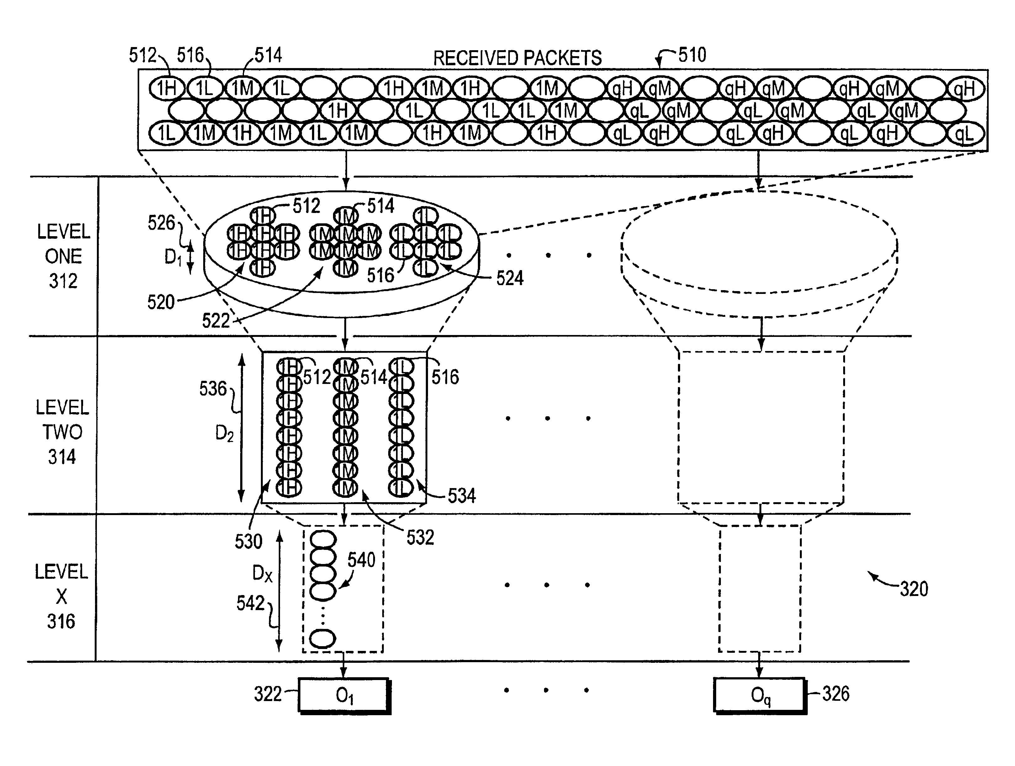
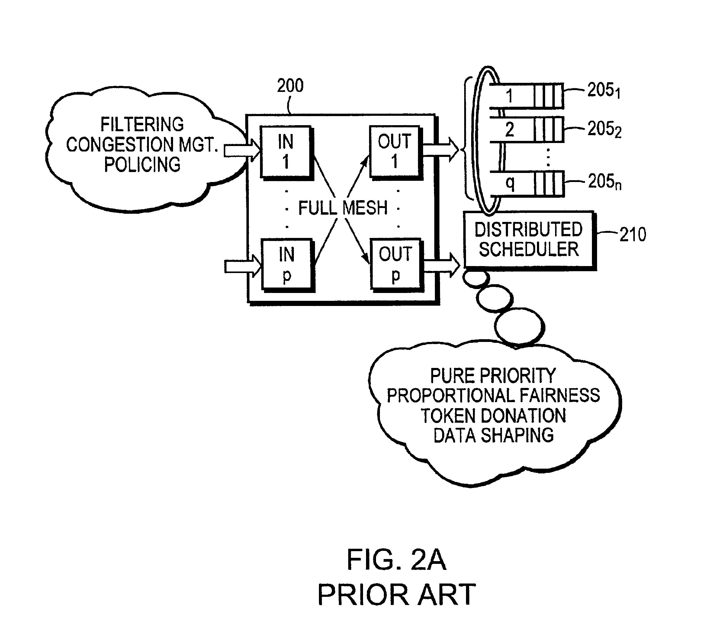
The present invention utilizes a hierarchically organized output-queuing system that permits scaling of full-mesh architectures to bandwidth aggregation levels ordinarily associated with partial-mesh systems. Moreover, the architecture of the present invention facilitates output-side traffic engineering control, thereby accommodating sophisticated de-queuing schemes that respect packet priority levels.

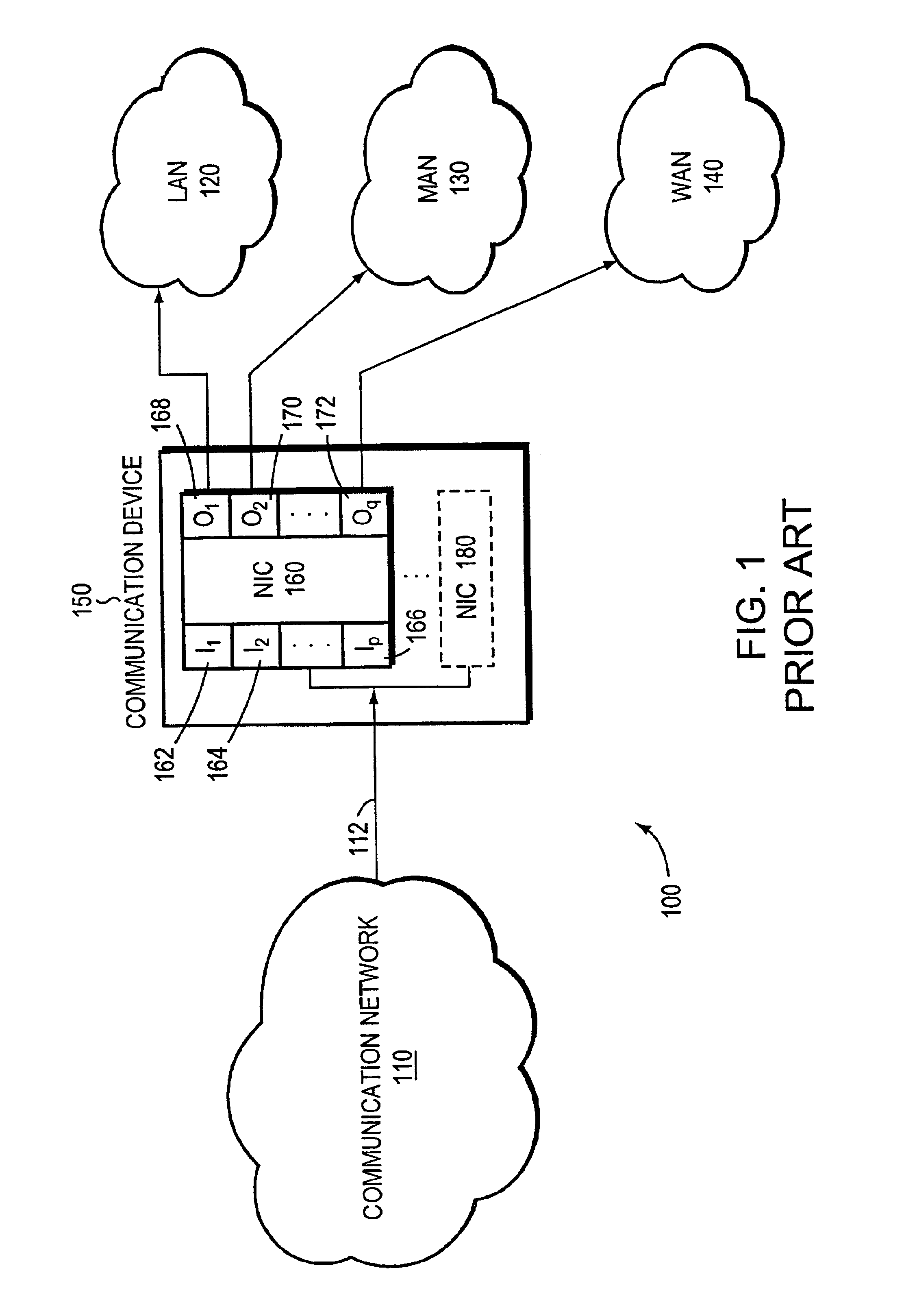
In one embodiment, a packet-buffering system and method incorporating aspects of the present invention is used in transferring packets from a series of input ports to a series of output ports in a communication device that is coupled to a communications network. The system buffers the packets received over the communications network in a hierarchical packet-buffering architecture, comprising two or more levels of memory / packet buffers rather than in a single memory as in the prior art.

A first packet buffer is organized into a first series of queues. The fi...


PUM


Abstract

The packet-buffering system and method of the present invention enables communication devices incorporating a full-mesh architecture to achieve bandwidth aggregation levels ordinarily associated with partial-mesh architectures. The packet-buffering invention uses a hierarchical memory structure having first and second packet-buffers to buffer packets between the input and output ports of the communication device. The received packets are organized by output port and priority level in the first packet buffer, which operates at the aggregate network rate of the communication device. The packets are then funneled to second packet buffers, having corresponding priority and output port assignments, at less than the aggregate network rate and which exhibit buffer depths that exceed that of the first packet buffer. The resulting hierarchical output-queued, packet-buffering system enables a communication system that exhibits a high degree of differentiated services with bandwidth guarantees and at high aggregation levels without experiencing head-of-line blocking.

Description

FIELD OF THE INVENTIONThe present invention relates generally to communication systems, and in particular to movement of data flows in packet-based communication architectures.BACKGROUND OF THE INVENTIONData communication involves the exchange of data between two or more entities interconnected by communication links. The data can be, for example, information transferred among computers or voice transmissions between individuals. In packet-based systems, data is communicated as discrete packets or frames of data according to predefined protocols; the protocols define how the packets are constructed and treated as they travel from source to destination, and facilitate re-assembly of the original message from the packets.The rapid proliferation of Internet communication, as well as rising demand for traditional telecommunication services, have taxed the ability of carriers to handle the resulting escalation in traffic. Carriers have increasingly turned to fiber-optic media, which offe...

Claims


Application Information

Patent Timeline
IPC IPC(8): H04L12/56
CPCH04L12/5693H04L47/2441H04L47/6205H04L49/9052H04L49/90H04L47/6215H04L49/3036H04L47/50
Inventor WOO, LEON K.RYAN, ROBERT
Owner EXTREME NETWORKS INC
Why Eureka
Try Eureka