Electromagnetic fuel injection valve

a fuel injection valve and electromagnetic technology, applied in the direction of fuel injection apparatus, wear-reducing fuel injection, feed system, etc., can solve the problems of inability to meet the performance and durability of electromagnetic fuel injection valves, unstable open and closed attitudes of valve assemblies, adverse effects on the accuracy of fuel injection, etc., to achieve excellent stabilization of open and closed attitudes, enhanced dimensional accuracy, and increased sliding resistan

Inactive Publication Date: 2005-02-08
KEIHIN CORP
View PDF8 Cites 12 Cited by
  • Summary
  • Abstract
  • Description
  • Claims
  • Application Information

AI Technical Summary

Benefits of technology

Accordingly, it is an object of the present invention to provide a an electromagnetic fuel injection valve, in which even if the sliding gap between the movable core and the guide portion for the movable core is minimized with their dimensional accuracies enhanced, an increase in sliding resistance cannot be brought about, and hence the valve assembly is excellent in stabilization of the opened and closed attitudes and in responsiveness, which can contribute to an improvement in low fuel consumption in an engine.
With the first feature, the surface roughness Rmax of the high-hardness coating formed on the outer peripheral surface of the valve assembly can be set at an extremely small value in a range of 0.05 to 0.2 μm; the sliding gap between the movable core and the guide portion for the movable core can be minimized with their dimensional accuracies enhanced without bringing about an increase in sliding resistance; and both the stabilization of the opened and closed attitudes and the responsiveness of the valve assembly can be established, thereby contributing to an improvement in low fuel consumption in an engine.
Moreover, the diamond-like carbon forming the high-hardness coating has a frictional coefficient smaller than that of a high-hardness coating formed by chromium plating, whereby an increase in sliding resistance of the valve assembly can be effectively suppressed.

Problems solved by technology

Moreover, the wear of the coating advances over a long period, and as a result the opened and closed attitudes of the valve assembly become unstable to exert an adverse effect to the accuracy of the injection amount of fuel.
Thus, the performance and the durability of the electromagnetic fuel injection valve cannot be satisfied.

Method used


Image

  • Electromagnetic fuel injection valve
  • Electromagnetic fuel injection valve
  • Electromagnetic fuel injection valve

Examples


Embodiment Construction

The present invention will now be described by way of a preferred embodiment with reference to the accompanying drawings.

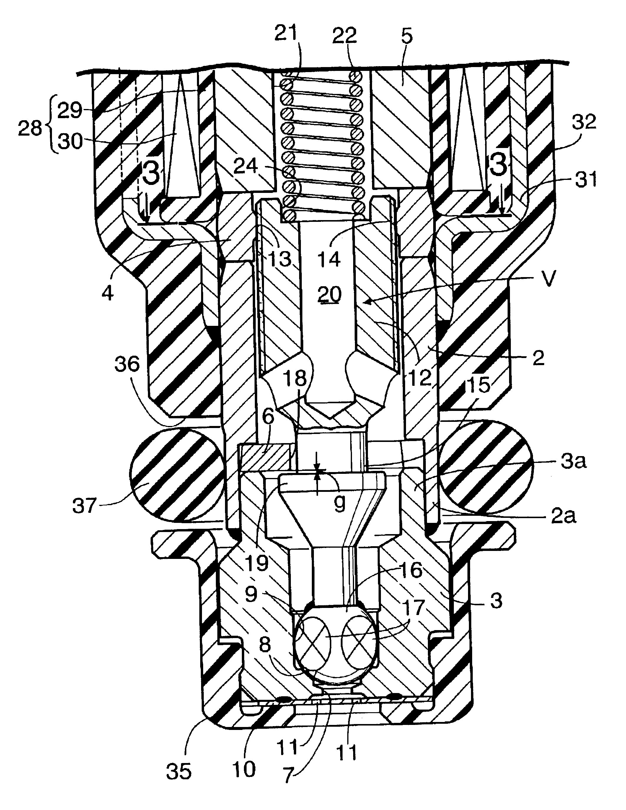
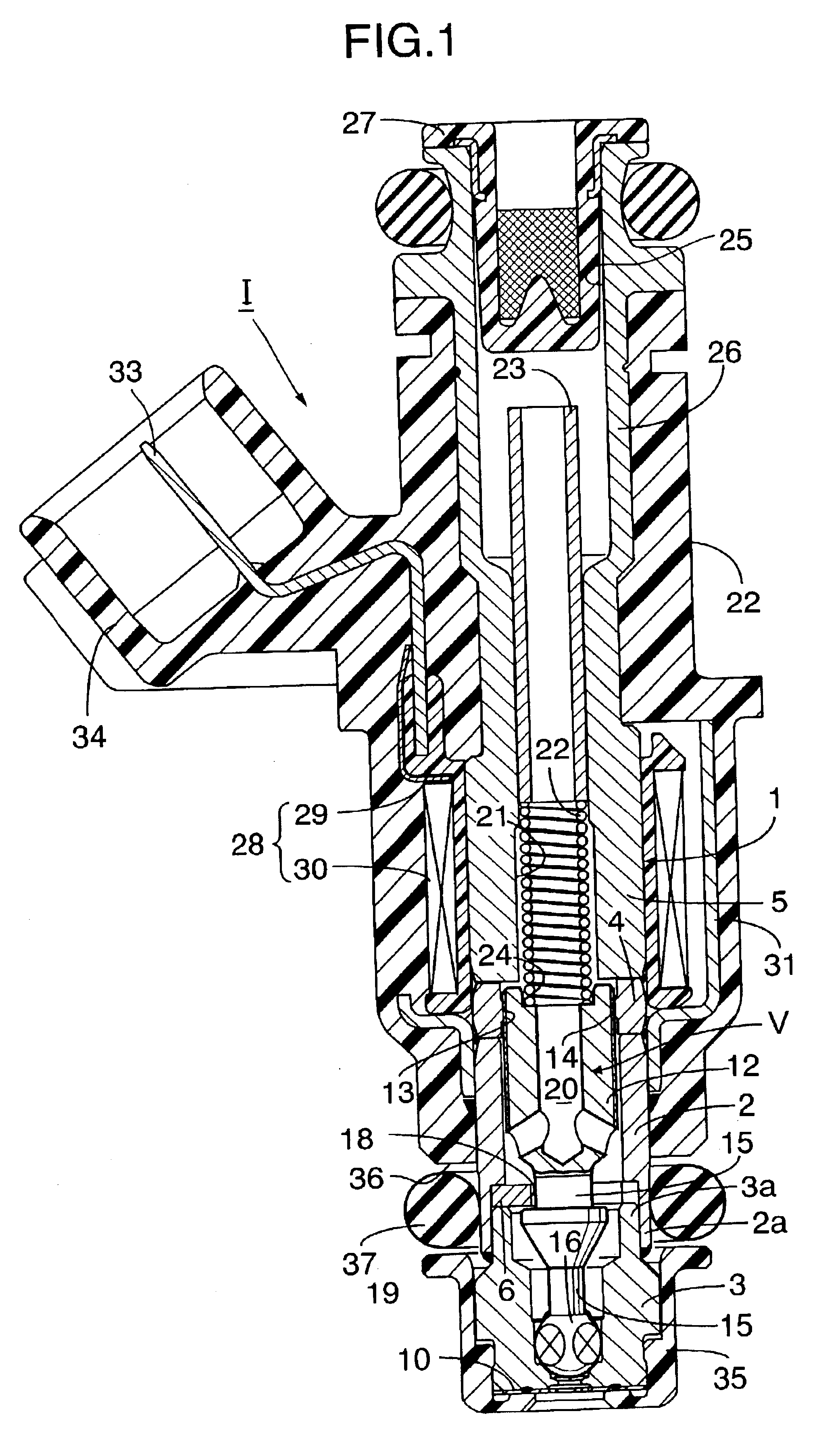
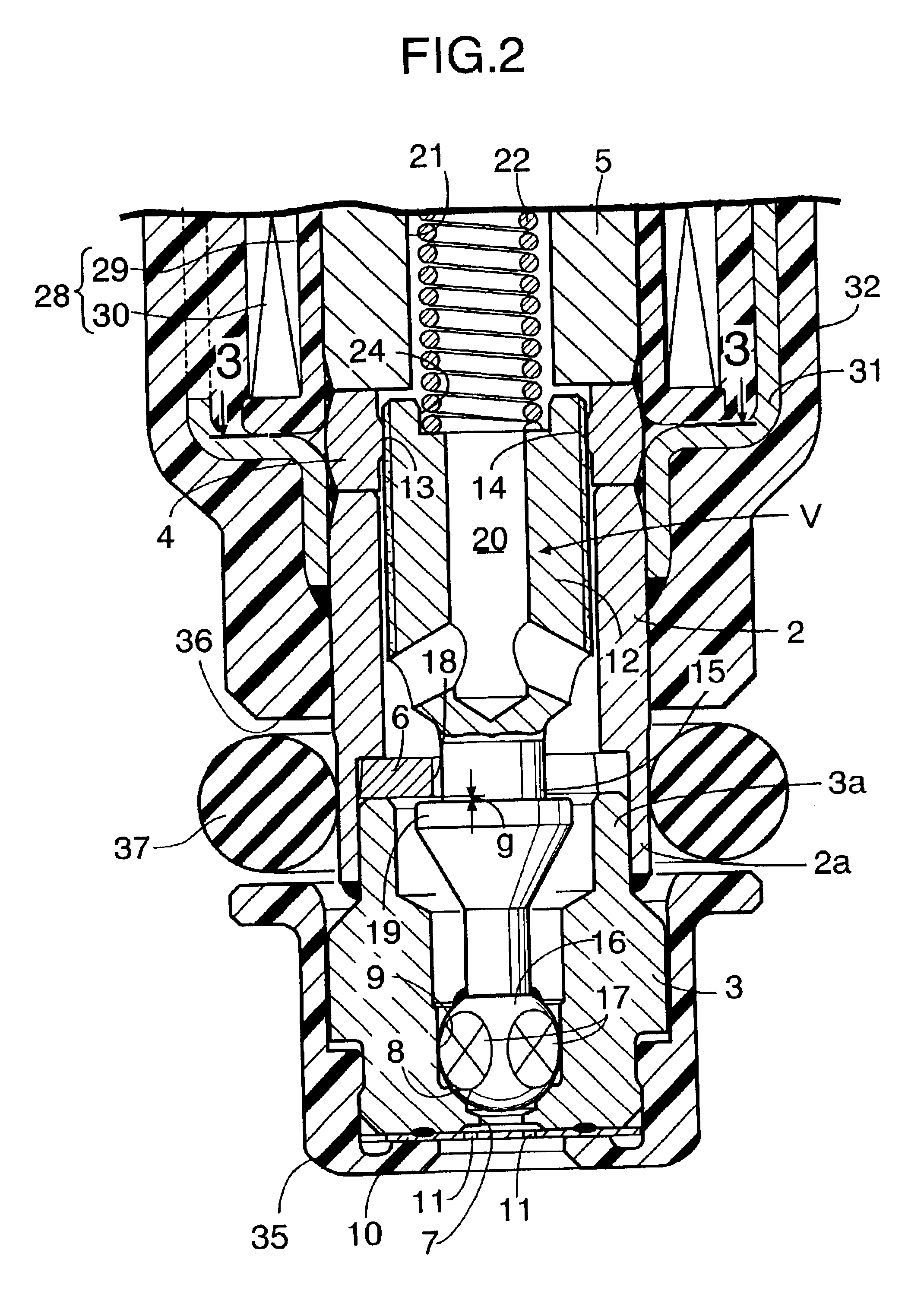
Referring to FIGS. 1 and 2, a casing 1 of an electromagnetic fuel injection valve I for an internal combustion engine is comprised of a cylindrical valve housing 2 (made of a magnetic material), a bottomed cylindrical valve seat member 3 liquid-tightly coupled to a front end of the valve housing 2, and a cylindrical stationary core 5 liquid-tightly coupled to a rear end of the valve housing 2 with an annular spacer 4 interposed therebetween.

The annular spacer 4 made of a non-magnetic metal, e.g., a stainless steel, and the valve housing 2 and the stationary core 5 are placed to abut against opposite end faces of the annular spacer 4, and liquid-tightly welded to the opposite end faces over their entire peripheries.

A first fitting tube portion 3a and a second fitting tube portion 2a are formed at opposed ends of the valve seat member 3 and the valve housing 2, resp...


PUM


Abstract

An electromagnetic fuel injection valve includes a valve housing coupled to at one end thereof to a valve seat member; a stationary core coupled to the other end of the valve housing; and a valve assembly comprised of a movable core slidably accommodated in the valve housing, and a valve member connected to the movable core through a rod portion and adapted to cooperate with the valve seat. In the electromagnetic fuel injection valve, the valve housing is provided with a guide portion on which the valve assembly is axially slidably carried, and a high-hardness coating of diamond-like carbon including silicon is formed on an outer peripheral surface of the valve assembly contacting with the guide portion. The surface roughness Rmax of the high-hardness coating is set in a range of 0.05 to 0.2 μm. Thus, it is possible to achieve the stabilization of opened and closed attitudes of the valve assembly and the responsiveness of the valve assembly, thereby contributing an improvement in low fuel consumption in an engine.

Description

BACKGROUND OF THE INVENTION1. Field of the InventionThe present invention relates to an electromagnetic fuel injection valve mainly used in a fuel supply system for an internal combustion engine, and particularly to an improvement in an electromagnetic fuel injection valve including: a valve seat member having a valve seat at one end; a valve housing coupled at one end thereof to the other end of the valve seat member; a stationary core coupled to the other end of the valve housing; and a valve assembly comprised of a movable core slidably accommodated in the valve housing so that it is opposed to the stationary core, and a valve member connected to the movable core through a rod portion and adapted to cooperate with the valve seat, the valve housing being provided with a guide portion on which the valve assembly is axially slidably carried, the valve assembly having a high-hardness coating formed on its outer peripheral surface contacting the guide portion to provide a wear resista...

Claims


Application Information

Patent Timeline
Patent Type & Authority Patents(United States)
IPC IPC(8): F02M61/00F02M61/16F02M51/06F02M61/12F02M63/00
CPCF02M51/0614F02M51/0682F02M61/168F02M61/166F02M61/12F02M61/165F02M2200/9038F02M2200/02F02M2200/505
Inventor NAGAOKA, TAKAHIROWATANABE, HIDEYUKIICHISE, SHINYA
Owner KEIHIN CORP
Why Eureka
Try Eureka