Drive system for motor vehicles

a technology for driving systems and motor vehicles, applied in the direction of machines/engines, engine starters, jet propulsion mounting, etc., can solve the problems of unfavorable air conditioning while the vehicle is stopped, the demand for air conditioners is even less favorable, and the power balance cannot be optimized with claw pole generators that are conventional today, so as to optimize fuel consumption and optimize the power balance of the motor vehicle. , the effect of optimizing the power supply

Inactive Publication Date: 2005-02-08
ROBERT BOSCH GMBH
View PDF11 Cites 43 Cited by
  • Summary
  • Abstract
  • Description
  • Claims
  • Application Information

AI Technical Summary

Benefits of technology

The drive system for motor vehicles according to the invention, has the advantage that with the main drive, the secondary assembly drive, and the starter generator, three components for optimizing the power balance in the motor vehicle can be used, especially for optimizing fuel consumption, both individually and in combination, both for driving the motor vehicle and for supplying the secondary assemblies. With this drive concept, beyond a medium driving power demand, a powerful internal combustion engine is to be used in the main drive train in particular, while an internal combustion engine of lesser power is to be used in particular to drive the secondary assemblies. This secondary assembly drive also serves to start the engine in the main drive train, or as a drive at low power demand both to support the engine in the main drive train and at very high driving power demand (kick-down). With the provisions according to the invention, not only comfort-related requirements such as independent air conditioners, but also fast, quiet starting and high on-board electrical system power, as well as sharply reduced fuel consumption, can all be achieved at substantially less expense cost than in motor

Problems solved by technology

In addition, this power is sometimes needed even in engine idling, that is, for crankshaft speeds of less than 700 rpm, which cannot be achieved with the claw pole generators that are conventional today.
In terms of the charge balance, however, concepts that use a starter generator to start the engine in the main drive train both in cold starting and in the start and stop mode are extremely critical, especially, since when the electrical system power

Method used


Image

  • Drive system for motor vehicles
  • Drive system for motor vehicles

Examples


Embodiment Construction

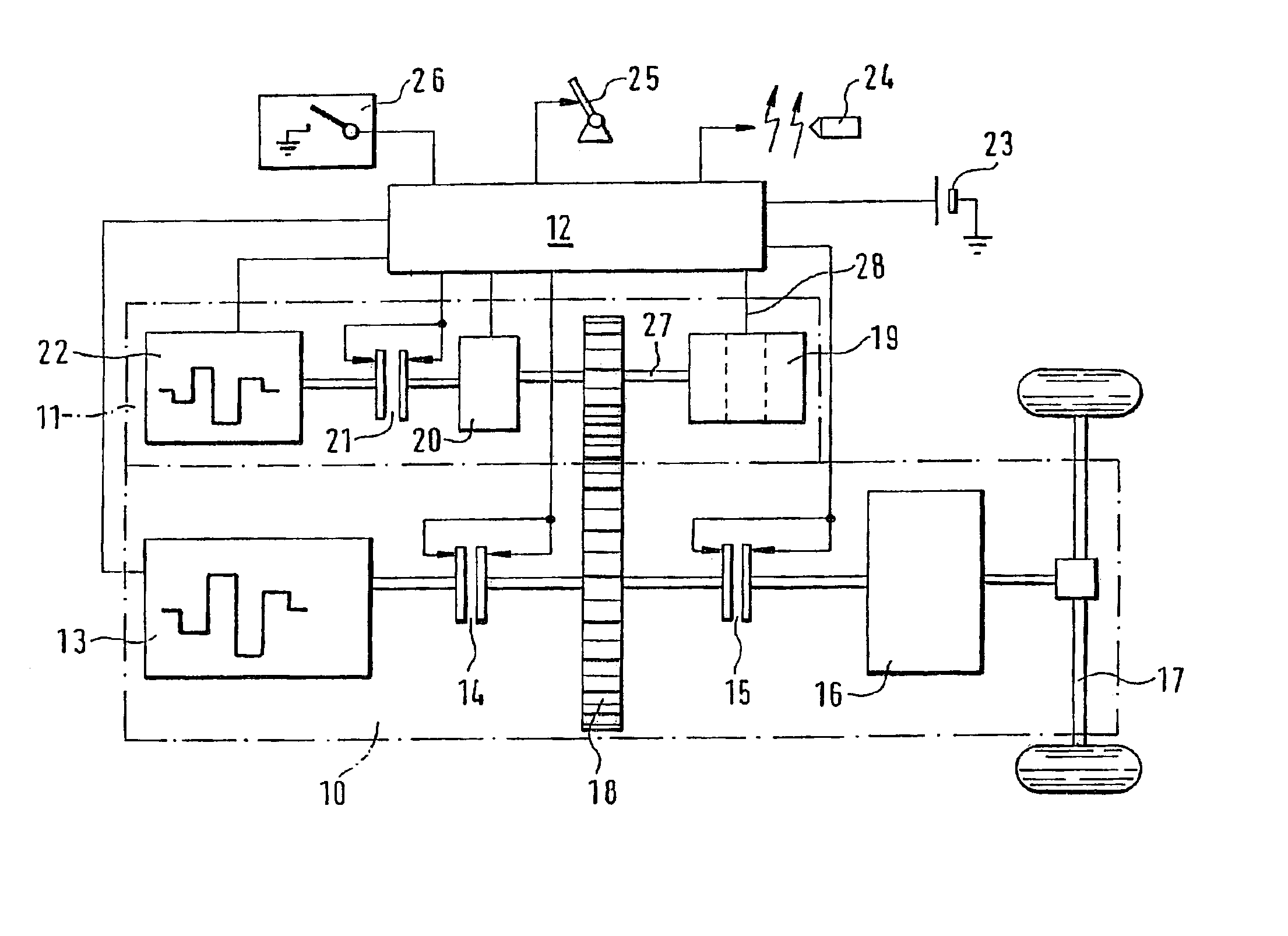
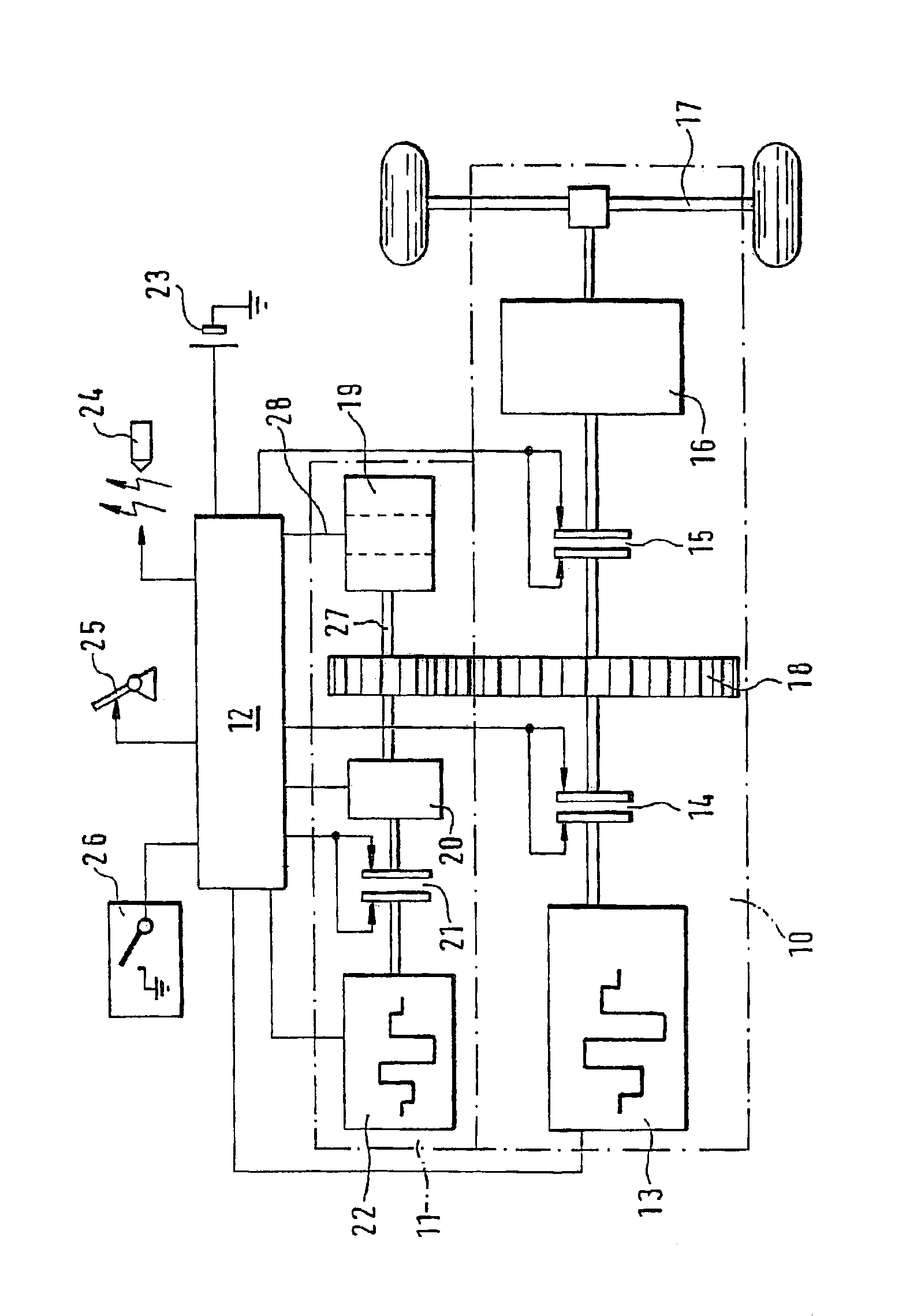
From the drawing, a drive system for motor vehicles can be seen that comprises a main drive train 10 and a secondary drive train 11, as well as a common electric controller and supply means 12 in the on-board electrical system of the motor vehicle. The main drive train includes an internal combustion engine 13 as its main drive, an auxiliary clutch 14 at the power takeoff of the engine 13, a driving clutch 15, and a conventional transmission 16 downstream of it, whose output shaft is solidly connected to a driving axle 17 of the motor vehicle. Between the driving clutch 15 and the auxiliary clutch 14 in the main drive train 10, there is an intermediate gear 18, which connects the main drive train 10 to the secondary drive train 11. To the extent that they are not driven electrically, at least one secondary assembly 19 to be driven, and optionally operating even if the main drive is shut off or the vehicle is stopped, such as a coolant pump, an oil pump for the lubricant system in th...


PUM


Abstract

A drive system for motor vehicles, in particular having an internal combustion engine (13) as a main drive, a driving clutch (15), a transmission (16) and at least one drive axle (17) in the main drive train (10), furthermore having a secondary drive train (11) and having secondary assemblies (19) which can be disposed in the secondary drive train (11), the secondary drive train (11) being capable of being coupled to the main drive train, and having an electric machine operating as a starter generator (20), characterized in that the secondary drive train (11) has its own secondary assembly drive (22) which can be coupled to the starter generator (20), and that the secondary assembly drive (22) and the starter generator (20) can be coupled to the driving axle (17) of the motor vehicle either individually or jointly, with or without the main drive (13), to drive the motor vehicle.

Description

BACKGROUND OF THE INVENTIONThe invention relates to a drive system for motor vehicles.In the very great majority of motor vehicles, an internal combustion engine is provided in their drive system as the main drive; this engine is coupled to one or more driving axles in the main drive train via a driving clutch and a transmission. Secondary assemblies, such as pumps, compressors, air conditioners, and electric consumers, such as power controls, are increasingly used in motor vehicles; they are driven via a secondary drive train that is coupled with the main drive train of the motor vehicle.It is also known, for reducing environmental pollution, to use hybrid drives in motor vehicles; then the drive system has both an internal combustion engine and an electric machine for selectively driving the motor vehicle. Once again, the internal combustion engine and the electric machine are located in the main drive train of the motor vehicle, and only the internal combustion engine is used to ...

Claims


Application Information

Patent Timeline
IPC IPC(8): B60K5/08B60K6/04B60K6/00B60K5/00B60K25/02B60K25/00F02N11/04B60K6/48B60K17/02B60K17/04B60W10/02B60W10/30B60W20/00F02B73/00F02N7/10
CPCB60K5/08B60K6/48B60K25/02B60L11/14B60W10/02F02N11/04B60W10/30B60L2240/36Y10T477/20B60W20/00Y02T10/6221Y02T10/7077Y10S903/946Y02T10/70B60L50/16Y02T10/62Y02T10/7072B60K2006/268B60W20/40B60W2510/0676
Inventor AHNER, PETERACKERMANN, MANFRED
Owner ROBERT BOSCH GMBH
Why Eureka
Try Eureka