System and method of producing thin-film electrolyte

a thin-film electrolyte and electrolyte technology, applied in the direction of non-aqueous electrolyte cells, sustainable manufacturing/processing, flat cell grouping, etc., can solve the problems of inability to use lithium metal as the anode, limited operating temperature range (10 to 70° c.) and market access still hindered

Inactive Publication Date: 2005-02-08
JOHNSON IP HLDG LLC
View PDF37 Cites 86 Cited by
  • Summary
  • Abstract
  • Description
  • Claims
  • Application Information

AI Technical Summary

Benefits of technology

A process for producing a thin film electrolyte layer comprises the steps of providing a plasma source coupled to a supply of plasma gas so as to emit a plasma stream that is directed to a substrate positioned adjacent the plasma source, vaporizing a volatile lithium containing precursor, vaporizing a volatile phosphate containing precursor, transporting the vaporized volatile lithium containing precursor to the plasma source, transporting the vaporized volatile phosphate containing precursor to the plasma source, and expelling the vaporized volatile lithium containing precursor and vaporized volatile phosphate containing precursor from the plasma source and into the plasma stream emitted from the plasma source. The volatile lithium containing precursor and volatile phosphate containing precursor are prevented from mixing with the plasma gas prior to the gas being expelled from the plasma source as a plasma stream.

Problems solved by technology

Although these batteries can be prepared in prismatic form, their market access is still hindered by the safety concerns and degassing problems associated with liquid electrolyte used in the batteries.
Although these new polymers may improve the room temperature properties of lithium ion batteries, their operating temperature range (10 to 70° C.) is still very limited.
Another disadvantage of these polymer-based batteries is that they cannot use lithium metal as the anode although lithium has the highest energy density among all anode materials.
This is because these polymers do not have enough mechanical strength to prevent lithium dendrite growth during the charge / discharge process.
However, the deposition rate from sputtering ceramic targets typically is low, at approximately 100 Å / min for LiPON film.
Therefore, the cost of producing LiPON films is still prohibitively high for large-scale applications.
For example, Vereda et al (Fernado Verda, Ronald B. Goldner, Terry E. Hass, and Peter Zerigian, Electrochemical and Solid-State Letters, 5(11) A239 (2002)) and Jenson et al (Mark Lynn Jenson and Victor Henry Weiss, U.S. patent application Ser. No. 815,983 / 09 Mar. 23, 2001) used an Ion Beam Assisted Deposition method to prepare LiPON films, but this method is difficult to scale up due to high equipment cost.
Attempts to deposit electrolyte films by reactive electron beam evaporation in N2 environment were not successful.
In summary, polymer electrolyte films still cannot satisfy the requirement for many advanced applications due to their limited operating temperature range and instability.
Although solid electrolyte (LiPON) developed by Bates et al can overcome this instability problem, the high cost of the sputtering process has hindered its large-scale applications.

Method used


Image

  • System and method of producing thin-film electrolyte
  • System and method of producing thin-film electrolyte
  • System and method of producing thin-film electrolyte

Examples


example i

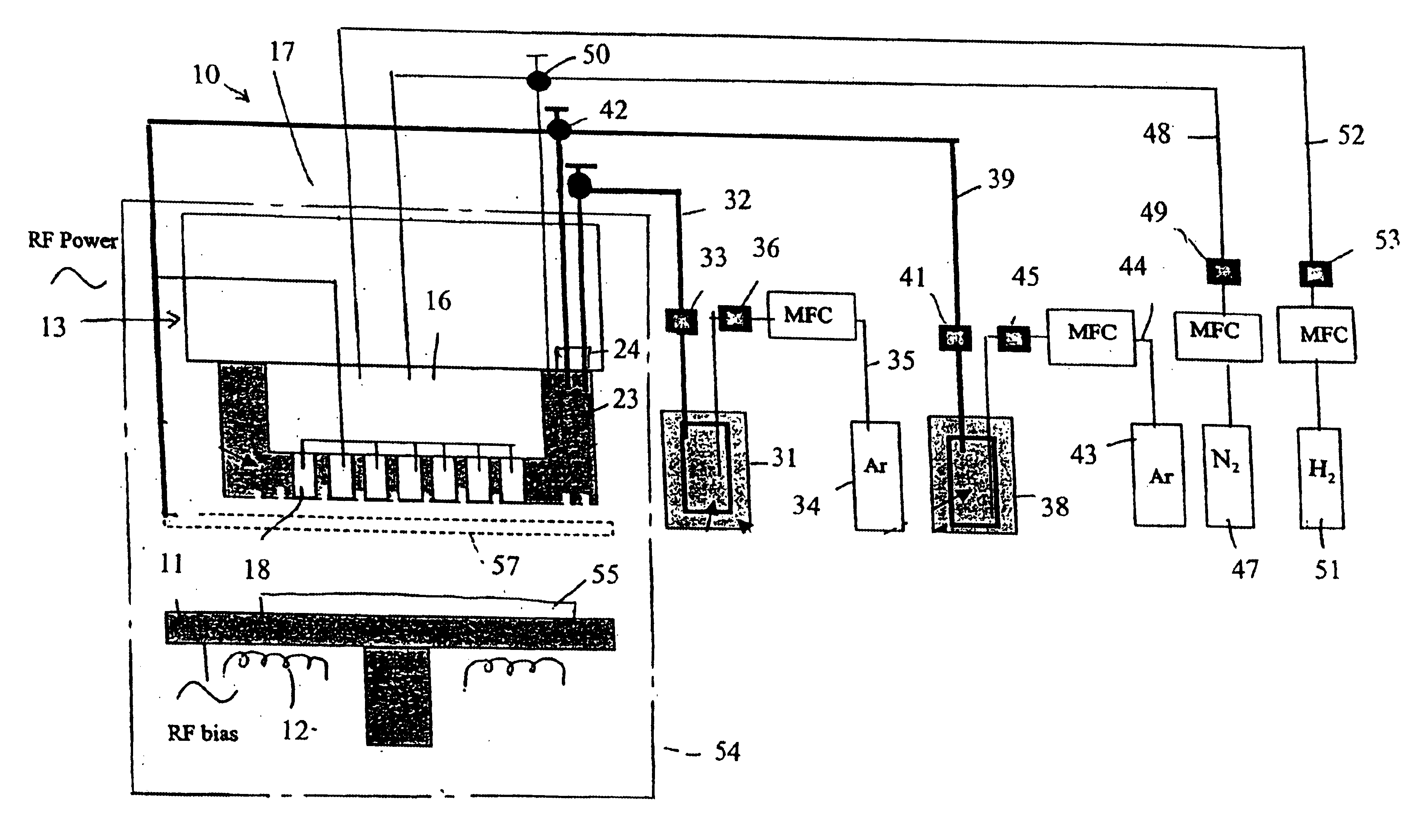
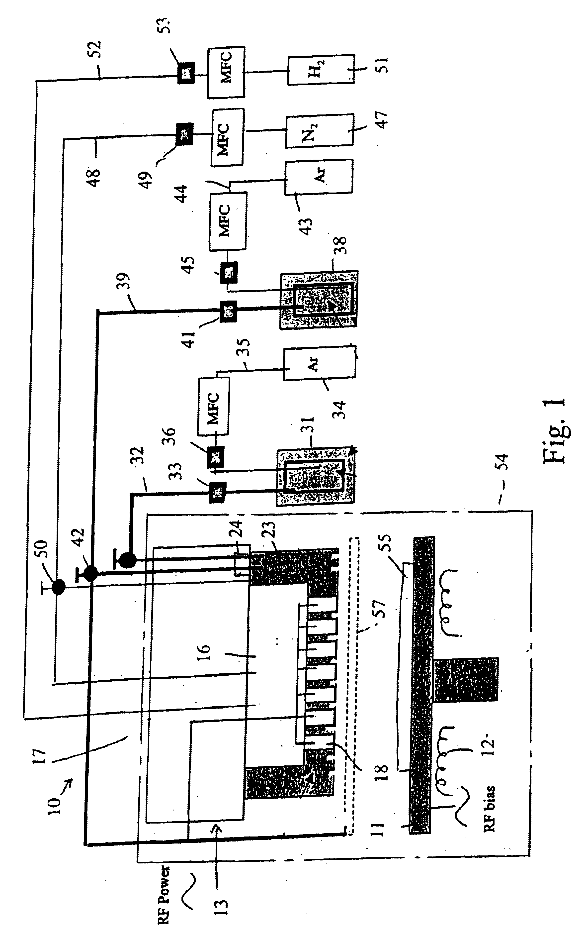
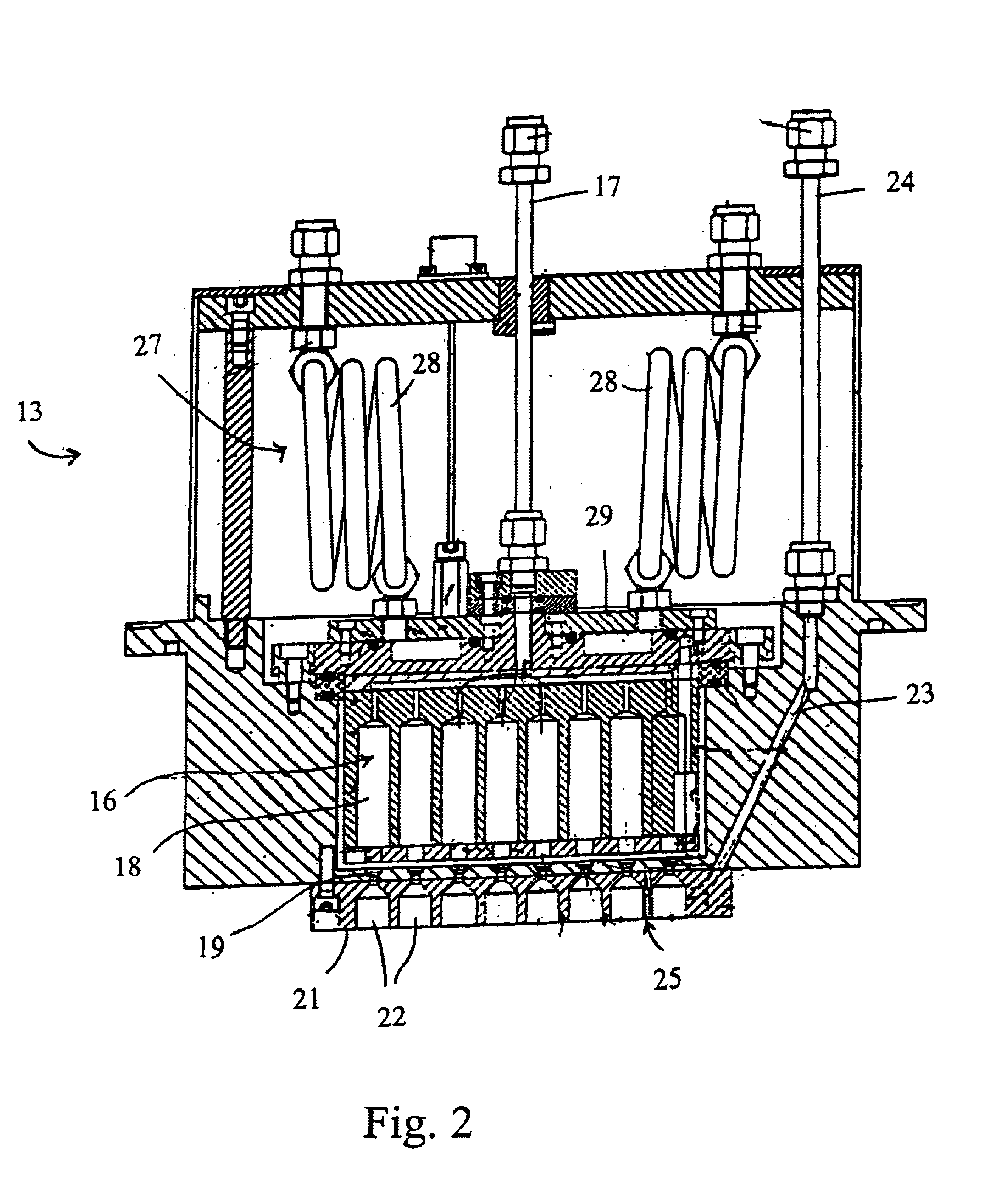
In one experiment, lithium tert-butoxide (LiTBO) and triethylphosphate OP(OC2H3)3 (TEPO) were used as lithium and phosphate precursors, respectively. The bubblers with lithium and phosphate precursors were maintained at 115 and 20° C., respectively. Argon was used as the carrier gas and the flow rates were set at 175 and 3 sccm for lithium and phosphate precursor, respectively. The lithium and phosphate bubbler pressures were 9.1 and 3.8 Torr, respectively. The precursors were introduced into the chamber through the secondary plenum. The gas lines 32 and 39 and showerhead or bottom plate 21 were heated to 120° C. to prevent condensation. Nitrogen was used as the plasma gas with a flow rate of 90 sccm. A small amount of hydrogen (1 sccm) was added to nitrogen gas to minimize the carbon content in the film. Too much H2 will largely reduce the deposition rate and have a detrimental effect on film properties. The gold-coated ceramic substrate (Al2O3), produced by Coors Ceramics Company ...

example ii

In another experiment, similar deposition parameters were used as those described in Example I except that the substrate temperature was set at 160° C. The XPS spectrum of the film is shown in FIG. 10. The film growth rate is 36 Å / min and exhibits an ionic conductivity of 3.5*10−7 S / cm.

example iii

In another experiment, similar deposition parameters were used as those described in Example I except that the lithium and phosphate bubbler pressures were 10.7 and 8.6 Torr, respectively. The film growth rate was increased to 71 Å / min. The impedance spectrum of the film is shown in FIG. 11. The ionic conductivity of film dramatically increased to 1.9*10−6 S / cm.


PUM

PropertyMeasurementUnit
operating temperatureaaaaaaaaaa
crystalline temperatureaaaaaaaaaa
conductivityaaaaaaaaaa

Abstract

A process of producing a thin film electrolyte is provided wherein a volatile lithium-containing precursor and a volatile phosphate-containing precursor are mixed into a plasma generated from a plasma source. The mixture is then deposited upon a substrate. The process is conducted with the use of a system (11) having a plasma source (13) having a primary plenum (16) and a secondary plenum (23). The primary plenum is in fluid communication with a source of nitrogen gas (47) and a source of hydrogen gas (51). The secondary plenum is in fluid communication with a first bubbler (31) and a second bubbler (38).

Description

TECHNICAL FIELDThis invention relates to systems for producing solid electrolytes and more specifically solid electrolytes utilized in thin-film batteries, and the method of producing such.BACKGROUND OF THE INVENTIONIntensive work has been done in the last two decades on the development of high performance lithium ion batteries, especially on polymer based lithium ion batteries (W. H. Meyer, Advanced Materials, V10. No. 6, 439 (1998); M. Z. A. Munish, in Handbook of Solid State Batteries and Capacitors, Chapter 19. Ed. By M. Z. A. Munish, World Scientific Pub. Singapore, 1995). These include two major strategies on using ion-conducting polymers as electrolyte in lithium batteries have been used. The first strategy is the development of highly conductive materials via the cross linking of mobile chains to form networks, which are then swollen by lithium salt solutions or electrolyte. The matrix in which the ion transport occurs is liquid-like. One example of gel electrolyte is the po...

Claims


Application Information

Patent Timeline
Patent Type & Authority Patents(United States)
IPC IPC(8): C23C16/513C23C16/30C23C16/50H01M10/052H01M10/0562H01M10/36
CPCC23C16/30C23C16/513H01M10/0562H01M10/052Y10T29/49115Y02E60/122Y02E60/10Y02P70/50
Inventor ZHANG, JI-GUANGMEDA, LAMARTINEMAXIE, ELESTON
Owner JOHNSON IP HLDG LLC
Why Eureka
Try Eureka