Phase-lock loop having programmable bandwidth

a phaselock loop and bandwidth technology, applied in the direction of pulse manipulation, pulse technique, generating/distributing signals, etc., can solve the problems of master clock signal jitter and other artifacts, unsatisfactory “beat” frequency, and undesirable video display artifacts, so as to reduce the pll bandwidth, and reduce the pfd gain

Inactive Publication Date: 2005-02-08
INTERSIL INC
View PDF4 Cites 26 Cited by
  • Summary
  • Abstract
  • Description
  • Claims
  • Application Information

AI Technical Summary

Benefits of technology

Providing such a suppression circuit in a PLL provides advantages that include reducing the PFD gain. By lowering the PFD gain, one lowers the PLL bandwidth such that one can use a filter capacitance that is small enough to be integrated onto a chip that includes the PLL. In addition, such a suppression circuit allows one to use a charge pump having a single output stage.

Problems solved by technology

If, however, these frequencies are different, undesirable “beat” frequencies can result.
Unfortunately, the beat frequency can cause undesirable artifacts to appear in a video display.
Because the PWM controllers 120a, 120b, and 120c have high-impedance clock inputs noise may cause jitter and other artifacts on the master clock signal.
Such jitter, artifacts, and signal delays may cause the PWM signals generated by the PWM controllers 120a, 120b and 120c to have different frequencies.
Again, having different frequencies may give rise to a beat frequency that may cause visual artifacts in the video display.
Furthermore, the master clock chip which takes up space on the graphics board 100 and, thus, increases component count, overall cost, and manufacturing complexity.
One problem with using a slave PLL, however, is that because it typically operates at a relatively low bandwidth (e.g. 100 Hz to 100 kHz) the PLL typically requires relatively large passive-filter components (typically a capacitor) to set the bandwidth.
Unfortunately, such an external component occupies space on the graphics board 100 and, thus, often increases the component count, overall cost, and manufacturing complexity of the graphics board 105.
Furthermore, the external component requires that the PWM controller chip 120 have an additional coupling pin, and thus often increases the size, cost, and manufacturing complexity of the PWM controller chip 120.
A problem with this technique, however, is that the multiple drive stages occupy a significant area of the PWM controller chip 120 that includes the PLL.

Method used


Image

  • Phase-lock loop having programmable bandwidth
  • Phase-lock loop having programmable bandwidth
  • Phase-lock loop having programmable bandwidth

Examples


Embodiment Construction

The following discussion is presented to enable a person skilled in the art to make and use the invention. The general principles described herein may be applied to embodiments and applications other than those detailed below without departing from the spirit and scope of the present invention. The present invention is not intended to be limited to the embodiments shown, but is to be accorded the widest scope consistent with the principles and features disclosed or suggested herein.

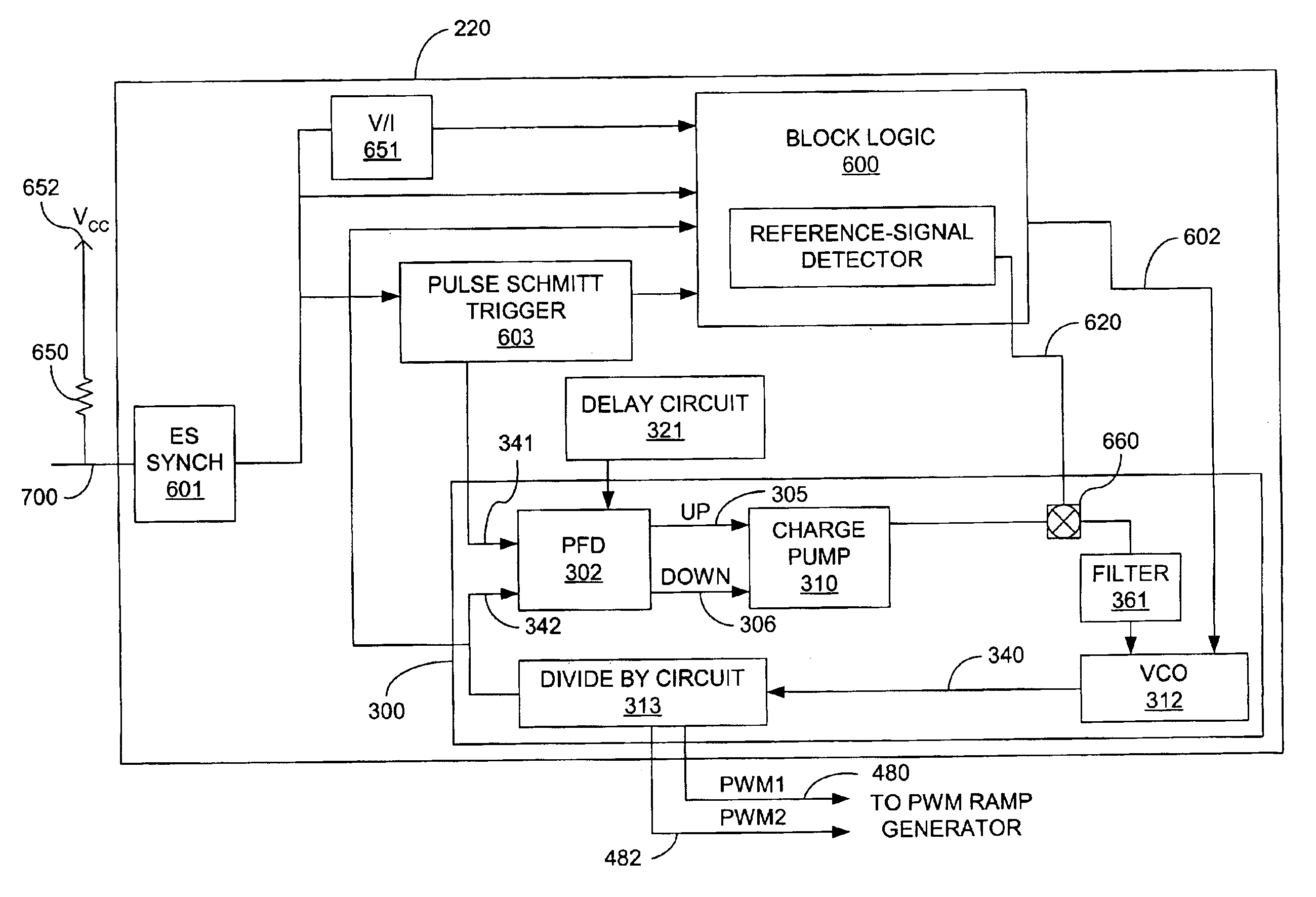
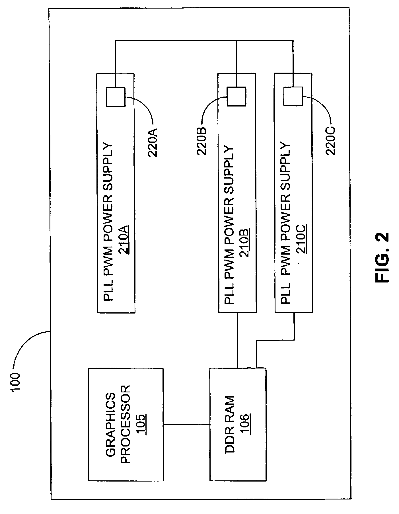
FIG. 2 shows a block diagram of a typical graphics board 100 that utilizes an embodiment of the invention. As was the case with respect to FIG. 1, the graphics board 100 includes a graphics processor 105 connected to a DDR RAM 106. Different from the prior art of FIG. 1, however, each of these components are driven by a PWM power supply 210a, 210b, and 210c having respective PWM controllers 220a, 220b, and 220c with integrated PLLs. The PWM controllers 220 are described below in conjunction with FIG. 6, a...


PUM


Abstract

A phase-locked loop having a programmable loop bandwidth is provided. A PLL comprises an oscillator operable to receive an error-correction signal and to generate an oscillator signal having a frequency that is related to the error-correction signal. The PLL further comprises a phase-frequency detector (PFD) coupled to the oscillator and operable to receive a reference signal and to generate the error-correction signal based upon a phase difference between the reference signal and a feedback signal derived from the oscillator signal. The PLL further comprises an error-correction signal suppression circuit coupled to the PFD and operable to control the loop bandwidth of the PLL by periodically enabling the PFD.

Description

BACKGROUND OF THE INVENTIONA graphics board is a printed-circuit board that typically includes at least one graphics processor and other electronic components that process and display graphics or other video data in a computer system. FIG. 1 is a block diagram of a conventional graphics board 100 that includes a graphics processor 105. Typically, one of the electronic components connected to the graphics processor 105 is a double-data-rate random-access memory (DDS RAM) chip 106. Both the graphics processor 105 and the DDR RAM 106 typically have high power requirements as compared to other electronic components. For example, the graphics processor 105 typically requires 5-15 amps (A) of power at 1.6 volts (V), and the DDR RAM 106 typically 5-10 A and 10-20 A at 1.25 V and 2.5 V, respectively. Because the processor 105 and DDR RAM 106 have such high power requirements, pulse-width-modulated (PWM) switching power supplies 110a, 110b, and 110c are typically provided for the graphics pr...

Claims


Application Information

Patent Timeline
Patent Type & Authority Patents(United States)
IPC IPC(8): G06F1/26G06F1/10H03L7/089H03L7/07H03L7/107H03L7/08H03L7/183H03L7/16H03K5/00H03K23/66
CPCG06F1/26H03K23/66H03L7/07H03L7/107H03L7/183G06F1/10H03L7/0891H03K2005/00286Y10S331/02
Inventor DICKMANN, MARK
Owner INTERSIL INC
Why Eureka
Try Eureka