High-voltage transformer

a transformer and high-voltage technology, applied in the direction of transformer/inductance details, inductances, coils, etc., can solve the problems of loose connection between the two coils, failure to reduce the distributed capacitance, and difficulty in miniaturizing the transformer to reduce the cost, and achieve the effect of satisfying the high-voltage output characteristics

Inactive Publication Date: 2005-02-08
MURATA MFG CO LTD
View PDF7 Cites 15 Cited by
  • Summary
  • Abstract
  • Description
  • Claims
  • Application Information

AI Technical Summary

Benefits of technology

In order to overcome the problems described above, preferred embodiments of the present invention provide an inexpensive, compact high-voltage transformer having satisfactory high-voltage output characteristics.
According to preferred embodiments of the present invention, the secondary coil connected to the diodes at both ends allows a reduction of the distributed capacitance in the secondary coil. In addition, the primary coils disposed on both sides of the secondary coil provide a close coupling between the primary and secondary coils. This enhances the high-voltage output characteristics and minimizes undesirable harmonics. Moreover, such a configuration allows a reduction in the number of components and processing steps. Therefore, preferred embodiments of the present invention provide an inexpensive, compact high-voltage transformer having satisfactory high-voltage output characteristics. Furthermore, the hole for holding the core is tapered, having advantages such as enhanced withstand voltage.

Problems solved by technology

Conventional high-voltage transformers unfortunately have a large number of components, making it difficult to miniaturize them to reduce their cost.
This bobbin resulted in a loose connection between the two coils.
In addition, in this bobbin, the secondary coil generates a pulse having the same amplitude as in a conventional bobbin, thus failing to reduce the distributed capacitance.
As a result, the bobbin exhibits poor high-voltage output characteristics, such as load characteristics and frequency characteristics.

Method used


Image

  • High-voltage transformer
  • High-voltage transformer
  • High-voltage transformer

Examples


Embodiment Construction

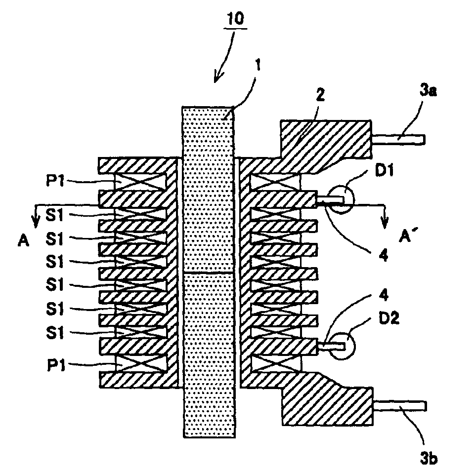
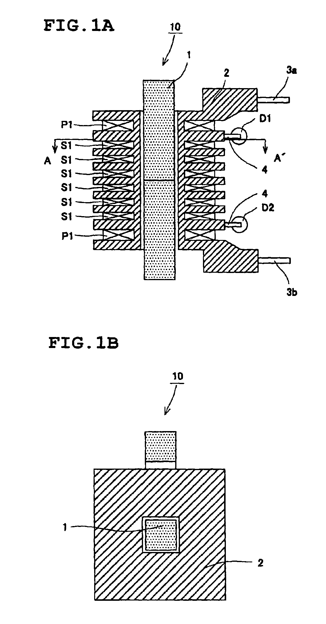
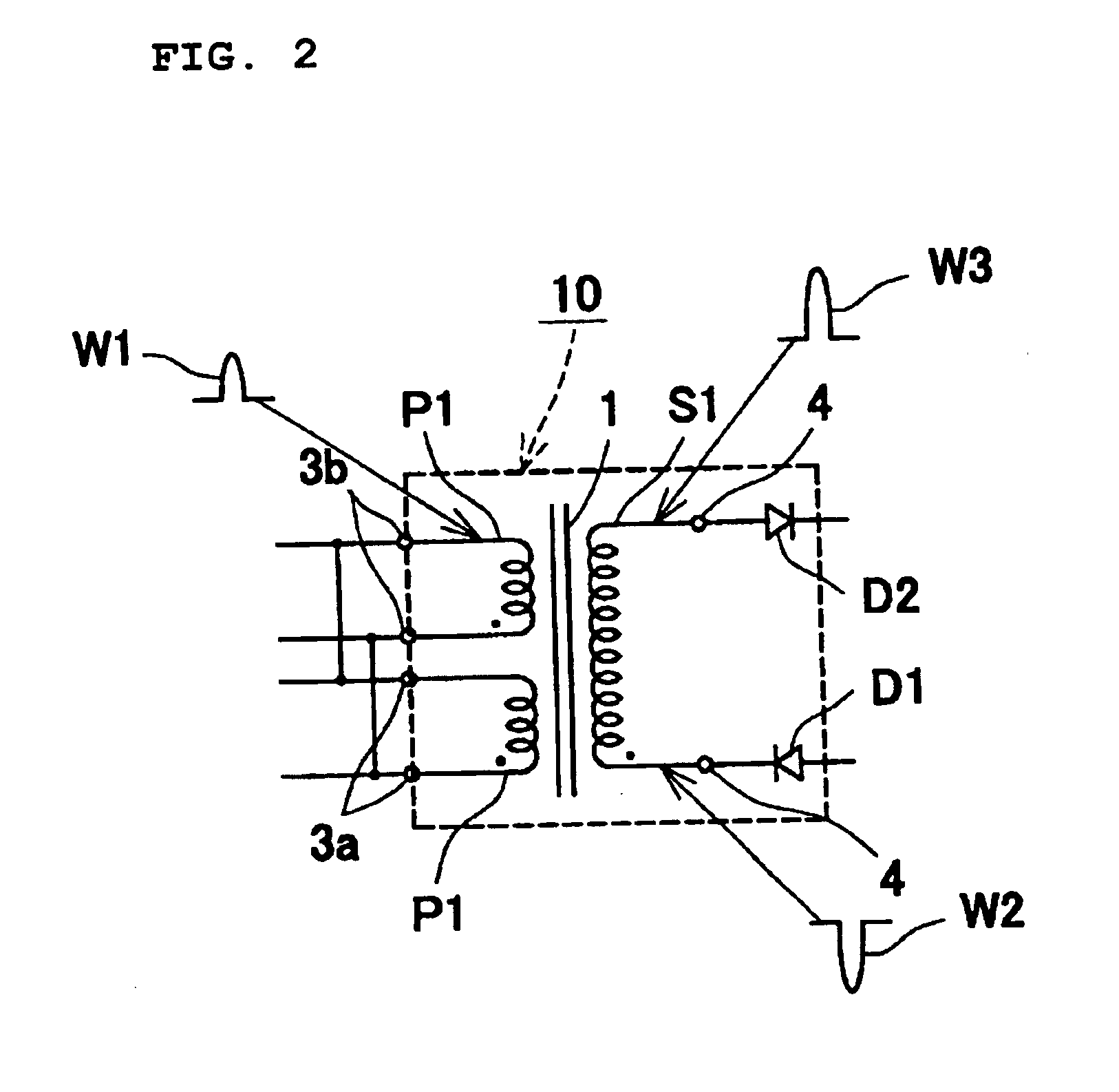
A first preferred embodiment of the present invention will now be described with reference to FIGS. 1A, 1B, and 2. FIG. 1A is a vertical sectional view of a high-voltage transformer; FIG. 1B, is a horizontal sectional view taken along a line A-A′ in FIG. 1A; and FIG. 2 is a circuit diagram showing pulses generated by the high-voltage transformer. Referring to FIGS. 1A, 1B, and 2, a high-voltage transformer 10 includes a bobbin 2 that holds a core 1 in its center. This core 1 is, for example, a horseshoe ferrite core with a substantially square sectional area of, for example, approximately 4 mm by 4 mm. The bobbin 2 is made of, for example, polybutylene terephthalate (PBT). This bobbin 2 has a hole for holding the core 1. The hole has a substantially square horizontal section and a uniform vertical section over the full length. The bobbin 2 has, for example, nine flanges arrayed along the central axis of the core 1. The nine flanges define eight winding grooves. For example, the oute...


PUM

PropertyMeasurementUnit
widthaaaaaaaaaa
widthaaaaaaaaaa
diameteraaaaaaaaaa

Abstract

A high-voltage transformer includes a bobbin that holds a core at its center. This bobbin has eight winding grooves arrayed along the central axis of the core. A primary coil is wound around each of two outermost winding grooves with a predetermined number of turns. A secondary coil is wound around the six winding grooves near the center with a predetermined number of turns, which are distributed among these winding grooves. The cathode of a diode is connected through a terminal to one end of the secondary coil where the winding starts, while the anode of another diode is connected through another terminal to the other end of the secondary coil where winding ends.

Description

BACKGROUND OF THE INVENTION1. Field of the InventionThe present invention relates to high-voltage transformers.2. Description of the Related ArtIn general, copy machines and printers use high-voltage power supplies. Such devices include a high-voltage transformer with a high-voltage output on the order of DC 10 KV.For example, Japanese Patent No. 3182799 discloses a high-voltage transformer of this type. This high-voltage transformer includes a transformer section and a voltage multiplier-rectifier circuit section. FIG. 4A is a sectional view showing bobbins of the transformer section. FIG. 4B is a circuit diagram showing pulses generated by the high-voltage transformer. Referring to FIG. 4A, a primary-coil bobbin 21 has a hole for holding a core in its center and two flanges arrayed along the central axis. These two flanges form a winding groove 22. One of the flanges has two terminals 23. A concentric secondary-coil bobbin 24 surrounds the periphery of the primary-coil bobbin 21. ...

Claims


Application Information

Patent Timeline
Patent Type & Authority Patents(United States)
IPC IPC(8): H01F27/32H01F27/30H01F38/00H01F38/42H01F5/02H01F27/00H01F27/40H01F27/26H01F27/28H01F30/00
CPCH01F27/325H01F27/306H01F5/02H01F27/266H01F38/42H01F27/40
Inventor NAGAI, TADAOSAIDA, YASUNOBUSUZUKI, TOSHIHIKO
Owner MURATA MFG CO LTD
Why Eureka
Try Eureka