Transflective type LCD and method for manufacturing the same

a technology of active matrix and transparent electrode, which is applied in the field of liquid crystal display, can solve the problems of increased overall power consumption, decreased time, and increased total weight, and achieve the effect of suppressing defects and improving the adhesiveness of transparent electrode film

Inactive Publication Date: 2005-02-08
NEC LCD TECH CORP
View PDF15 Cites 88 Cited by
  • Summary
  • Abstract
  • Description
  • Claims
  • Application Information

AI Technical Summary

Benefits of technology

In view of the above, it is a main object of the present invention to provide a transflective type LCD and method for manufacturing the same which can match the voltage-luminance characteristics of the panel in the transmission mode with those in the reflection mode and also which can suppress occurrence of a pixel defect caused by a reflection electrode film or a transparent electrode film.
In an configuration according to the present invention, the gap of the liquid crystal layer can be substantially equal in the transmission region and the reflection region so that the V-T characteristics in the transmission mode may agree with those in the reflection mode; also, by improving an adhesiveness of the transparent electrode film to protect the edge of the transparent electrode film securely, it is possible to suppress a defect from occurring owing to a developer during the PR (photo resist) step for forming the reflection electrode film.

Problems solved by technology

Although the transmission type LCD can use back-light to obtain bright display independently of the surrounding environments, a back-light source thereof typically has large power consumption of substantially a half of the total consumption thereof, thus contributing to an increase in the overall power consumption.
If the LCD is driven by a battery in particular, its operating time is decreased, while if a large sized battery is mounted thereto on the other hand, its total weight is increased, thus preventing improvements in size and weight thereof.
The reflection type LCD employs a reflecting plate in place of the back-light source to transmit / block the surrounding light reflected by the reflecting plate in order to control display, so that it need not have a back-light source, to thereby reduce its power consumption, size, and weight; at the same time, however, it is largely deteriorated in visibility problematically if the surroundings are dark.
Although the transmission type and reflection type LCDs have these advantages and disadvantages of their own, a back-light source is required in order to obtain stable display but inevitably increases power consumption of the LCDs if only it is used as the light source thereof.
In the above-mentioned conventional transflective type LCD, however, a gap of the liquid crystal layer 17 is different in the reflection region and the transmission region, that is, the gap with respect to the electrode is different on the side of the active matrix substrate 12 and on the side of the opposing substrate 16, so that the strength of an electric field applied on the liquid crystal cannot be equal in the various regions, to result in a change in luminance in these regions, thus problematically deteriorating the display quality.

Method used


Image

  • Transflective type LCD and method for manufacturing the same
  • Transflective type LCD and method for manufacturing the same
  • Transflective type LCD and method for manufacturing the same

Examples


first embodiment

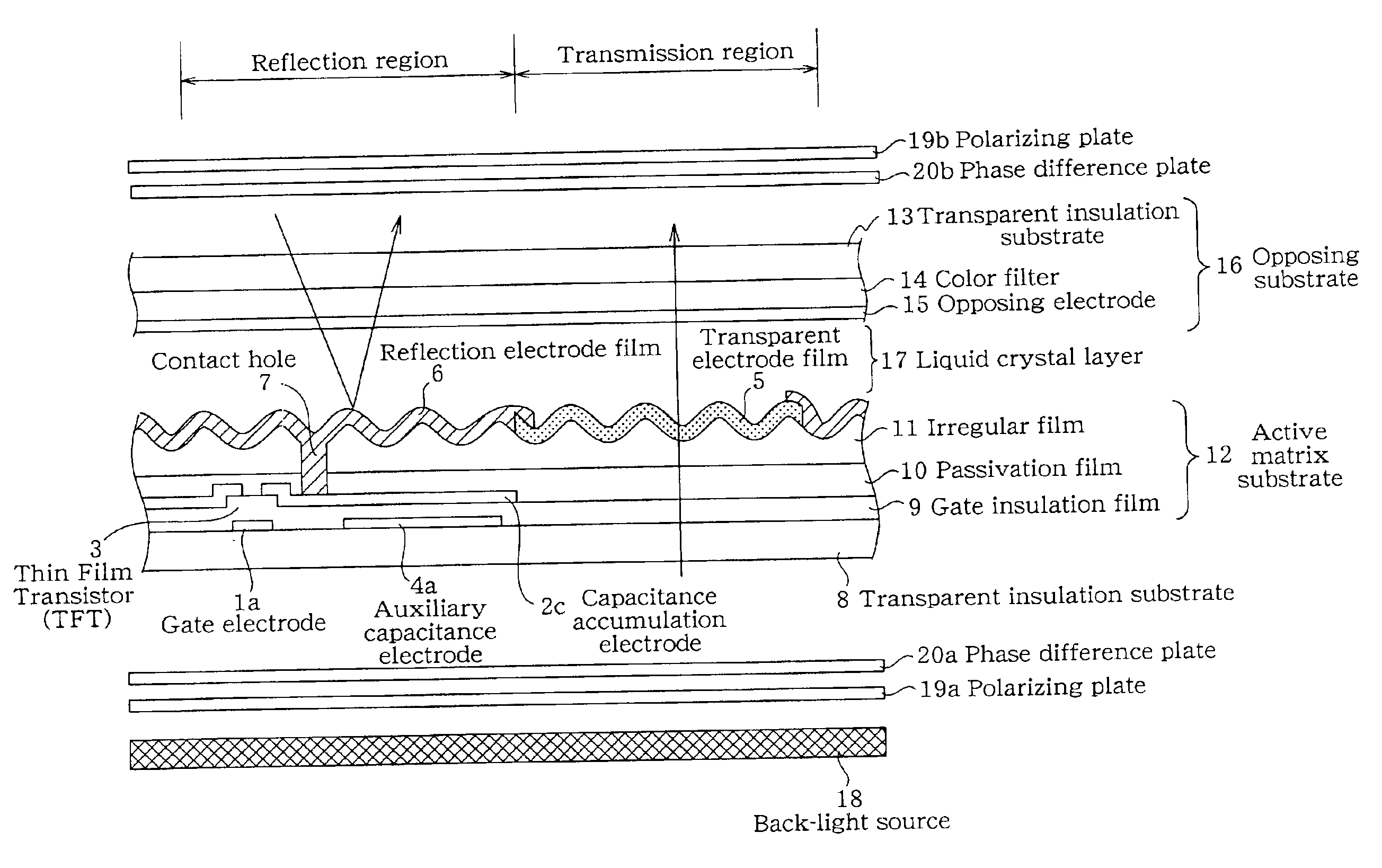
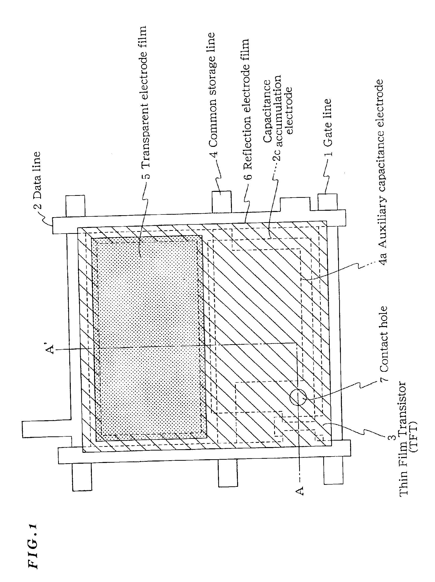
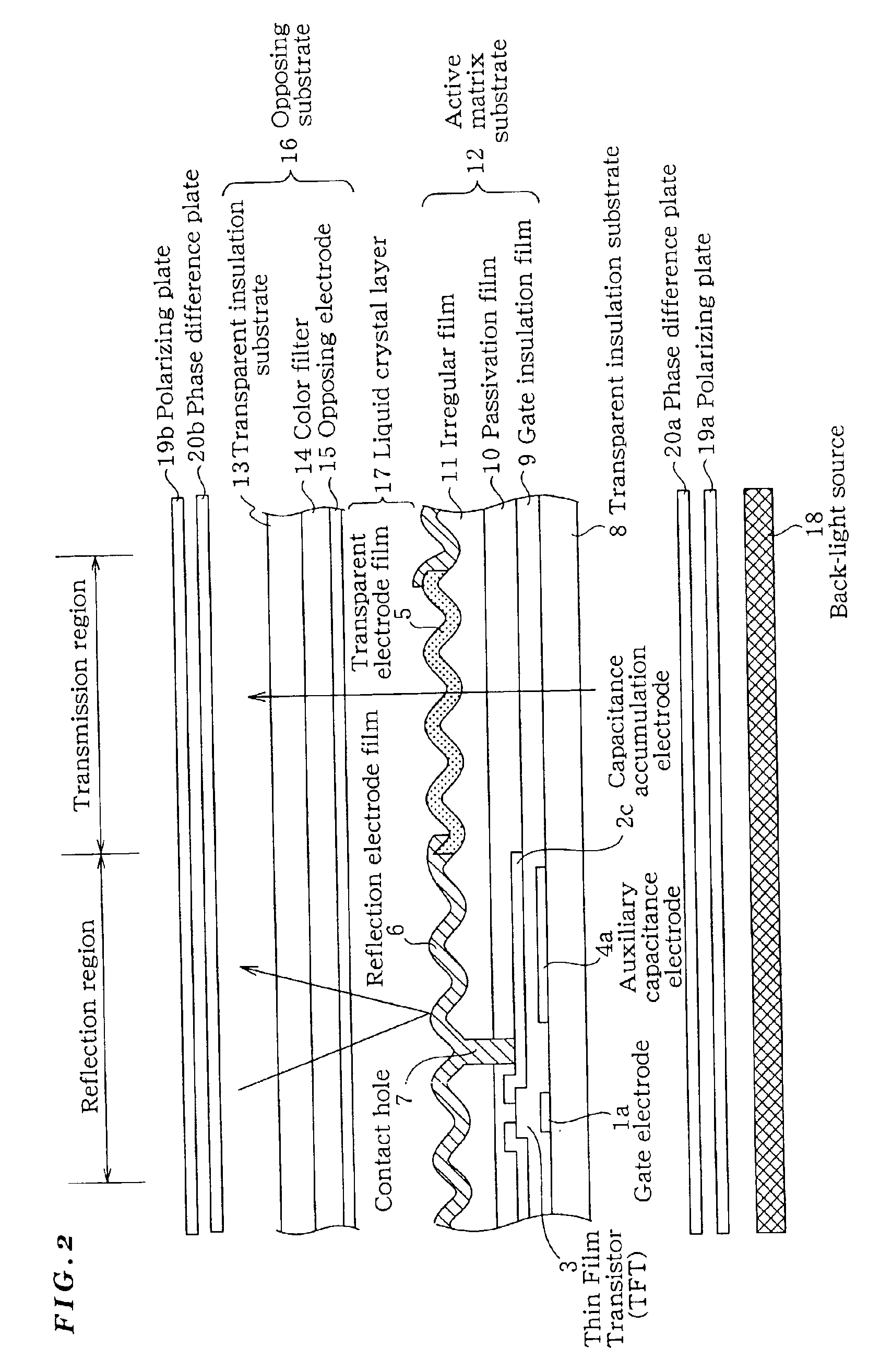
The following will describe a structure and a principle of the transflective type LCD related to the first embodiment of the present invention with reference to FIGS. 1-5. FIG. 1 is a plan view for showing a configuration of a transflective type LCD related to a first embodiment of the present invention, and FIG. 2 is a cross-sectional view in A-A′ line of FIG. 1. FIG. 3 is an illustration for showing a polarization state in each position of the transflective type LCD related to the first embodiment of the present invention, and FIG. 4 is a graph for showing a relationship between a twist angle and a gap. FIG. 5 are graphs for showing V-T characteristics under predetermined condition. Note here that the present embodiment features that an irregular film is formed also in the transmission region as in the reflection region in order to provide the same gap in these regions.

As shown in FIGS. 1 and 2, the transflective type LCD of the present embodiment comprises the active matrix subst...

second embodiment

The following will describe the transflective type LCD related to the second embodiment of the present invention with reference to FIGS. 6 and 7. The present embodiment features that to suppress a reaction between the transparent electrode film made of ITO etc. and the reflection electrode film made of Al / Mo etc., the positional relationship these electrode films is regulated.

The transflective type LCD 12 of the present embodiment comprises the active matrix substrate 12, the opposing substrate 16, and the liquid crystal layer 17 sandwiched by these substrates in such a configuration that on the outer sides of the active matrix substrate 12 and the opposing substrate 16 are respectively arranged the λ / 4 plates and the polarizing plates at the above-mentioned arrangement angle with respect to the optical axis. As the liquid crystal can be employed, for example, nematic liquid crystal NR523LA (Δn=0.086) made by Chisso Corp. with the above-mentioned settings of the gap value at 2.7 μm ...

third embodiment

The following will describe a transflective type LCD manufacturing method related to the third embodiment of the present invention with reference to FIGS. 8-10. Here, FIGS. 8-10 are drawings for explaining problems in production process of the active matrix substrate. Note here that the present embodiment features that the electric erosion reaction is suppressed from occurring between the transparent electrode film and the reflection electrode film.

In the above-mentioned second embodiment, as shown in FIG. 8B (expanded view of a defective portion of FIG. 8A), a problem that a developer soaks into the reflection electrode film 6 through its crack at the edge of the transparent electrode film 5 during a PR process for processing of the reflection electrode film 6 is solved by adjusting the planar positional relationship between the reflection electrode film 6 and the transparent electrode film 5. To suppress electric erosion from occurring between the reflection electrode film 6 and t...


PUM

PropertyMeasurementUnit
thicknessaaaaaaaaaa
twist angleaaaaaaaaaa

Abstract

In a transflective type LCD provided with a transparent region and a reflection region in each pixel, when an irregular film 11 is formed on an active matrix substrate 12 to form irregularities of a reflection electrode film 6, the irregular film 11 is specifically formed to almost the same film thickness in both the transparent region and the reflection region to provide substantially the same inter-substrate gap in these two regions so that they may have almost the same V-T characteristics and also the reflection electrode film 6 made of Al / Mo is formed so as to overlap with a transmission electrode film 5 made of ITO all around an outer periphery of the transmission electrode film 5 by a width of at least 2 μm, thus suppressing electric erosion from occurring between the ITO and Al substances at the edge of the transmission electrode film 5.

Description

BACKGROUND OF THE INVENTION1. Field of the InventionThe present invention relates to a Liquid Crystal Display (LCD) and method for manufacturing the same and, more particularly to, a transflective active-matrix type LCD having a transmission region and a reflection region in its pixel and method for manufacturing the same.2. Description of the Related ArtBecause of its features of a small and thin geometry and low power consumption, an LCD has been put to practical use in a variety of applications such as an OA apparatus and a portable apparatus. The LCDs are classified in a transmission type and a reflection type, the LCD of the transmission type of which has no function to emit light for itself unlike a CRT or an EL display and so is provided with a back-light source separately so that display may be controlled by transmitting / blocking the back-light of liquid crystal thereof.Although the transmission type LCD can use back-light to obtain bright display independently of the surrou...

Claims


Application Information

Patent Timeline
Patent Type & Authority Patents(United States)
IPC IPC(8): G02F1/1335G02F1/13G02F1/1362G02B5/08G02B5/30G02F1/1333G02F1/1343G02F1/136G02F1/1368G09F9/30G09F9/35H01L21/336H01L29/786
CPCG02F1/133555G02F1/133504G02F2001/136236G02F1/136227G02F1/136236A47J37/041A47J37/045A47J37/0745A47J37/0786A47J2037/0795
Inventor SAKAMOTO, MICHIAKIIHIDA, SATOSHIIKENO, HIDENORISHINOHARA, MASAKIKIMURA, SHIGERUMORIO, KENJISAEKI, KAZUROU
Owner NEC LCD TECH CORP
Why Eureka
Try Eureka