

Electronic timepiece with a contactless data communication function, and a contactless data communication system
- Summary
- Abstract
- Description
- Claims
- Application Information
AI Technical Summary
Benefits of technology
Problems solved by technology
Method used
Image

Examples
first embodiment
[First Embodiment]
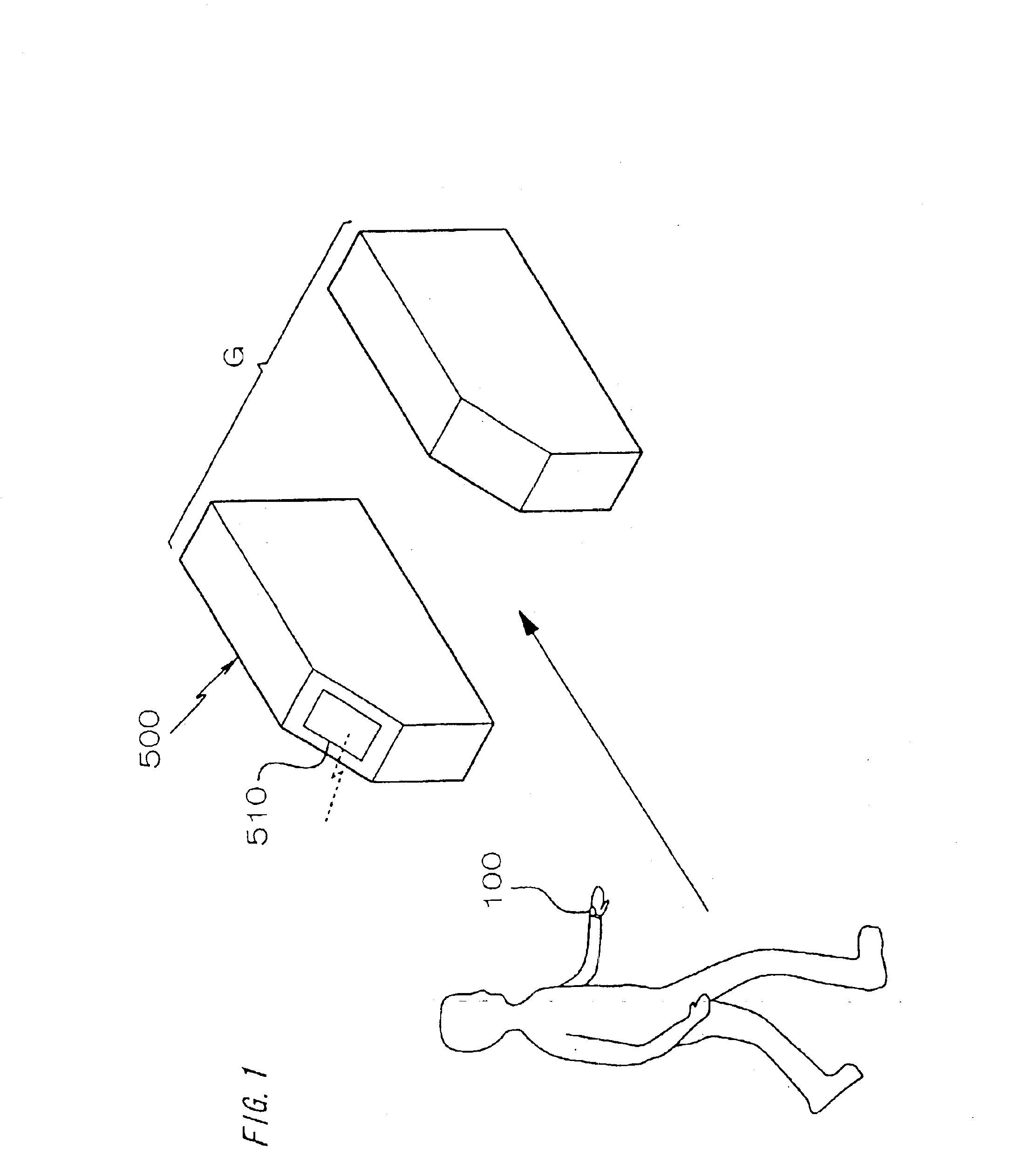
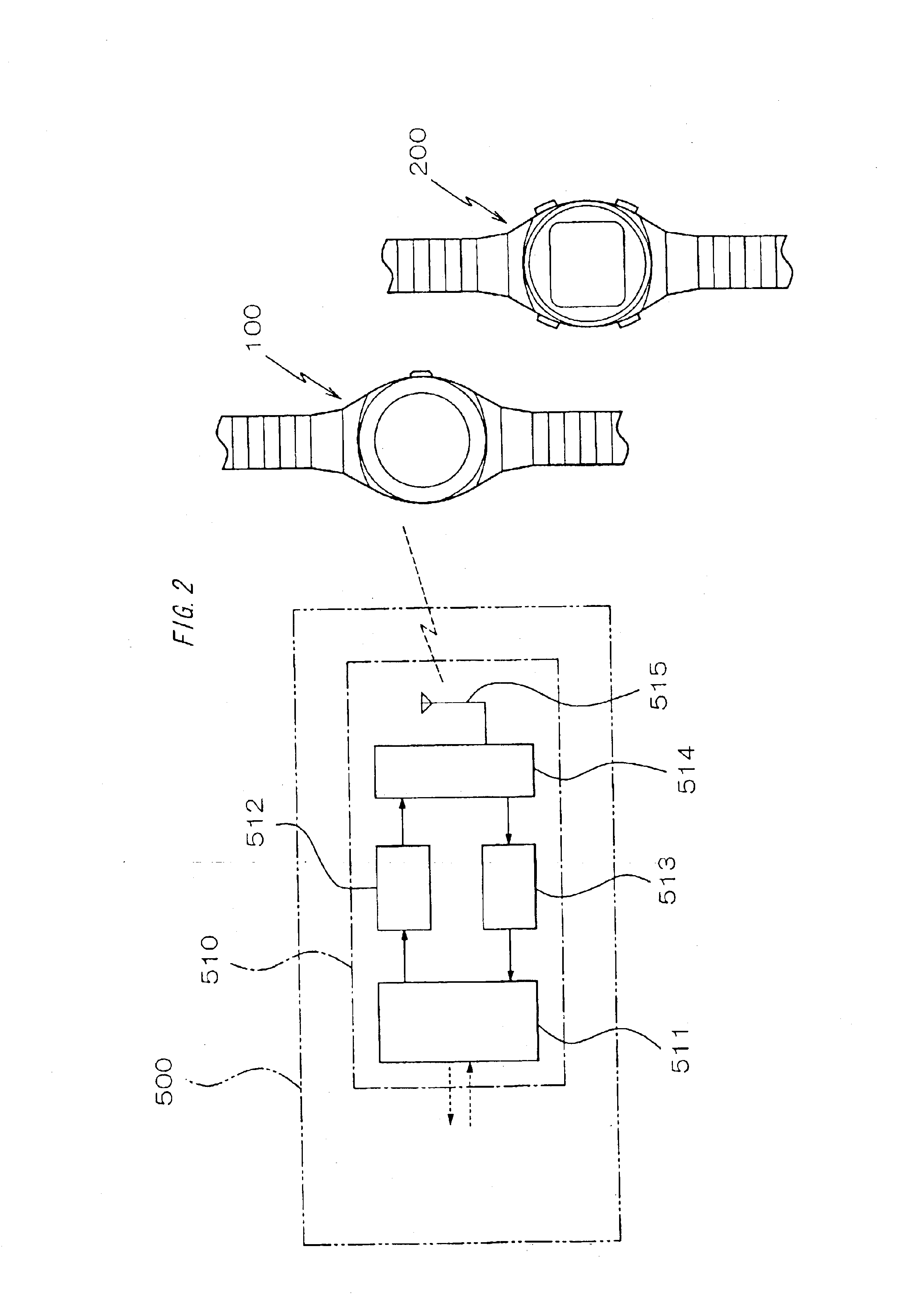
FIG. 1 is an oblique view showing the overall configuration of a contactless data communication system for an electronic watch 100 according to a preferred embodiment of the invention. This contactless data communication system has an electronic watch 100 and an external transceiver 510 capable of contactless data communication with this electronic watch 100. In the example shown here the external transceiver 510 is built into a ticket machine 500 located where one must pass (such as a gate) in order to board a train or lift, for example.
Contactless data communication between this electronic watch 100 and external transceiver 510 is generally low power RF communication using a 13.56 [MHz] or 125 [kHz] carrier wave (carrier signal) and limiting transmission output from both devices to a low level. Therefore, because the communication range is a range of several centimeters from the external transceiver 510, the user must pass the electronic watch 100 near the antenn...
second embodiment
[Second Embodiment]
An electronic watch 200 according to a second embodiment of the present invention is described next referring to FIG. 11. This embodiment is also configured for contactless data communication with an external transceiver 510 as shown in FIG. 1 and FIG. 2, and description of the configuration of external transceiver 510 is therefore omitted.
This electronic watch 200 has a case 201 made from a metal or other conductive material, crystal 202 mounted in a dial-side opening in case 201, back cover 203 made from an insulator mounted on the back-side opening in case 201, and a circuit board 204 disposed inside case 201. Mounted on this circuit board 204 are a clock IC 205, liquid crystal display panel or other display 206, quartz oscillator 207 for clock generation, and storage battery 208 such as a voltaic secondary cell or capacitor. In other words, this electronic watch 200 is a digital watch with a digital display 206.
A loop-shaped antenna 211 is formed on the surfac...
third embodiment
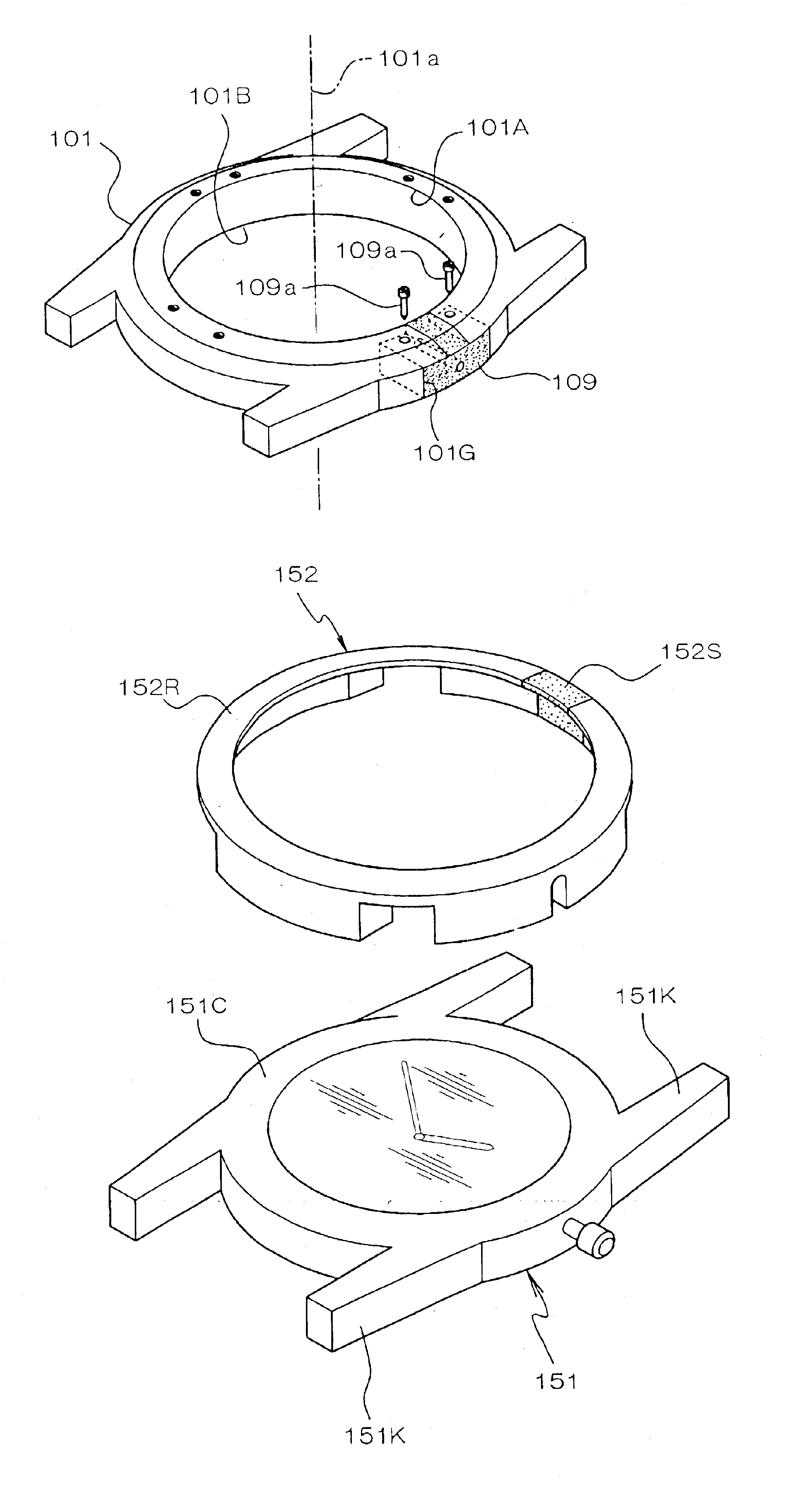
[Third Embodiment]
A third embodiment according to the present invention is described next with reference to FIG. 15. This embodiment forms an inside case 151 for housing the movement, for example, therein from a synthetic resin or other insulator. A housing part 151C and lugs 151K protruding from both sides of the housing part 151C for connecting a band not shown in the figures are disposed to this inside case 151.
An annular outside case 152 is fit to the outside surface of the above inside case 151, which is made from an insulator, so as to cover the housing part 151C. The outside case 152 is an annular frame with an L-shape in section. Multiple openings are disposed in the outside case 152 so that it does not contact the crown or other external operating members or the lugs 151K projecting to the outside from housing part 151C of inside case 151.
The outside case 152 has a ring part 152R that is a conductive member made from metal, for example. This ring part 152R is substantially ...
PUM
 Abstract
Description
Claims
Application Information