
Route/service processor scalability via flow-based distribution of traffic

a technology of flow-based traffic and routing, applied in the field of architecture, can solve the problems of unbounded amount of processing that performs services, wastes valuable processing time, and overflow of input and output queues waiting to transfer data, so as to increase the amount of “touch” and increase processing power. the effect of individual processors

Inactive Publication Date: 2005-02-08
CISCO TECH INC
View PDF225 Cites 25 Cited by
  • Summary
  • Abstract
  • Description
  • Claims
  • Application Information

AI Technical Summary

Benefits of technology

The invention provides a router architecture that can easily expand to accommodate future service growth and uplink connections. It allows for the addition of processors as needed without requiring a complete overhaul of the system's future hardware needs. The architecture also maintains packet ordering within each flow while still allowing for flexible routing among different processors.

Problems solved by technology

If the data transfer rate, or throughput rate, is not rapid enough, the end user of the required data must wait for it to arrive, wasting valuable processing time.
Also, input and output queues waiting to transfer data may overflow if information is being added more rapidly than it is being removed.
New services are being developed all the time, and thus the amount of processing that performing services requires is unbounded.
Eventually, the dedicated processor may no longer be able to keep up with the processing requirements of the line and the throughput rate will slow down.
This is an expensive solution.
In certain cases, for example a high-speed internet line or “uplink”, a processor may not even be available that can keep up with the interface rate of the high-speed line.
Current internet uplink rates such as Gigabit Ethernet (1 gigabit per second) are already becoming difficult to handle with a single dedicated processor.

Method used


Image

  • Route/service processor scalability via flow-based distribution of traffic
  • Route/service processor scalability via flow-based distribution of traffic
  • Route/service processor scalability via flow-based distribution of traffic

Examples


Embodiment Construction

order in each flow is maintained. Different flows may be sent to different processors.

BRIEF DESCRIPTION OF THE DRAWINGS

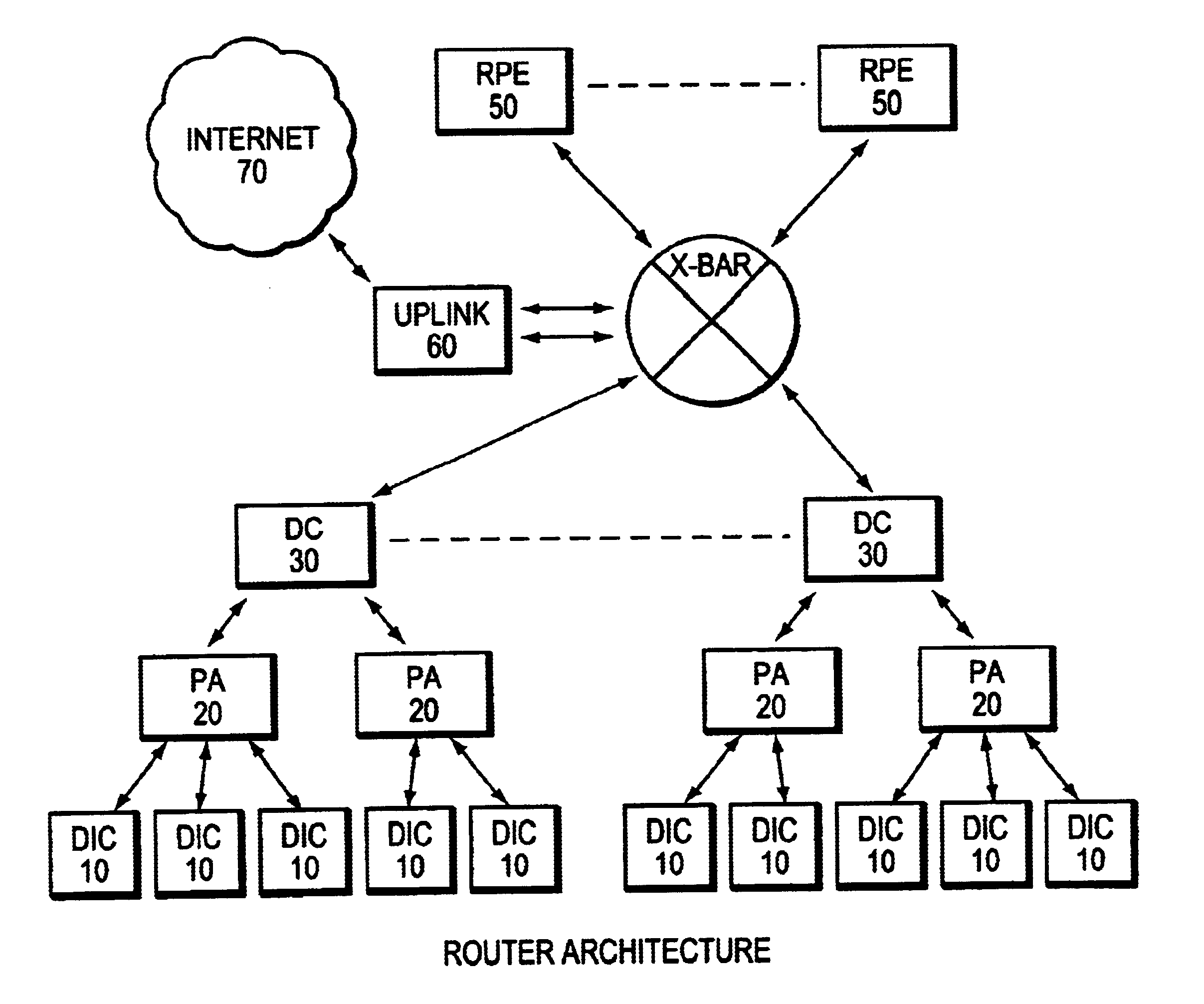
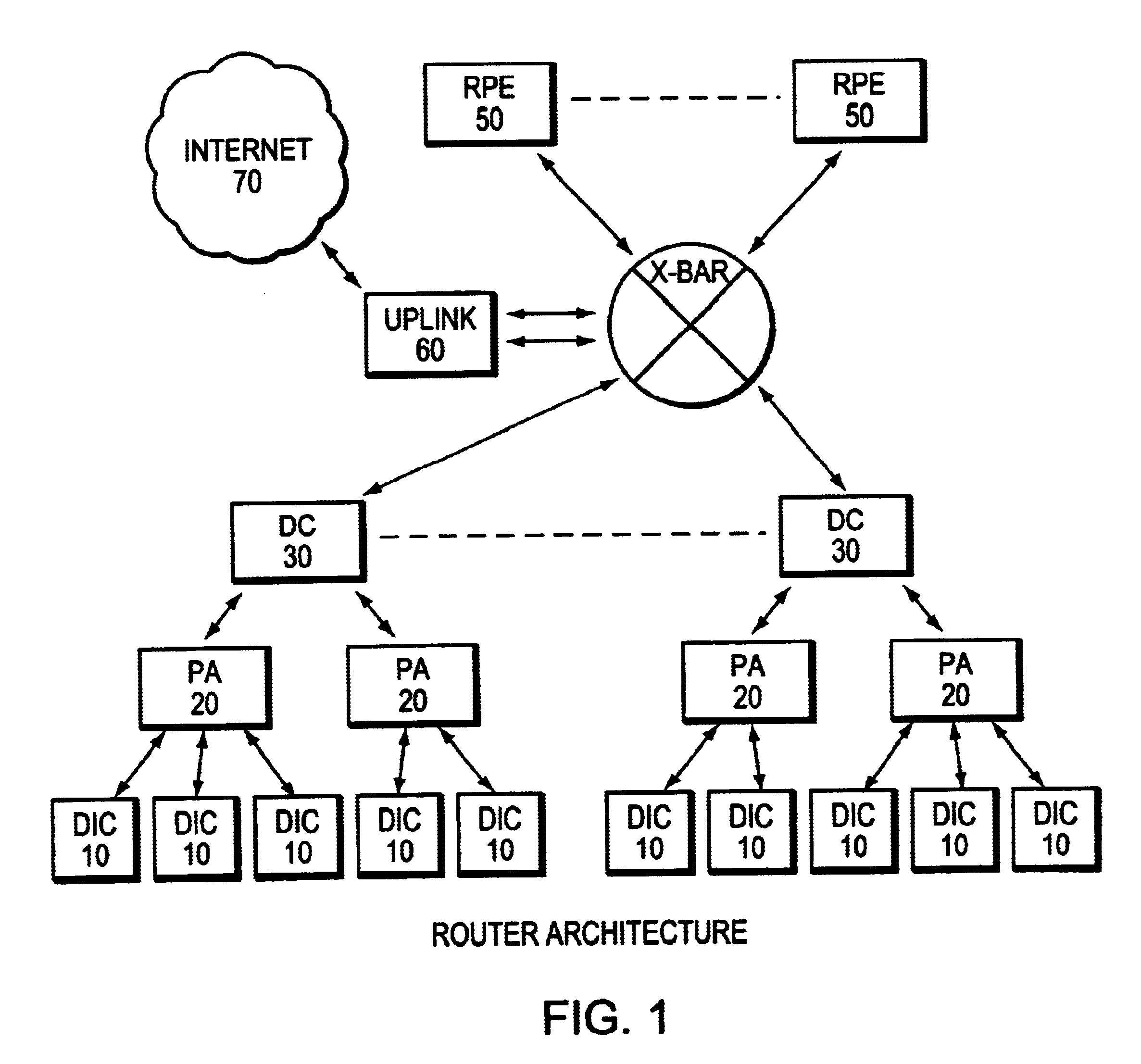
[0016]FIG. 1 shows a logical block diagram of the router architecture of the present invention.

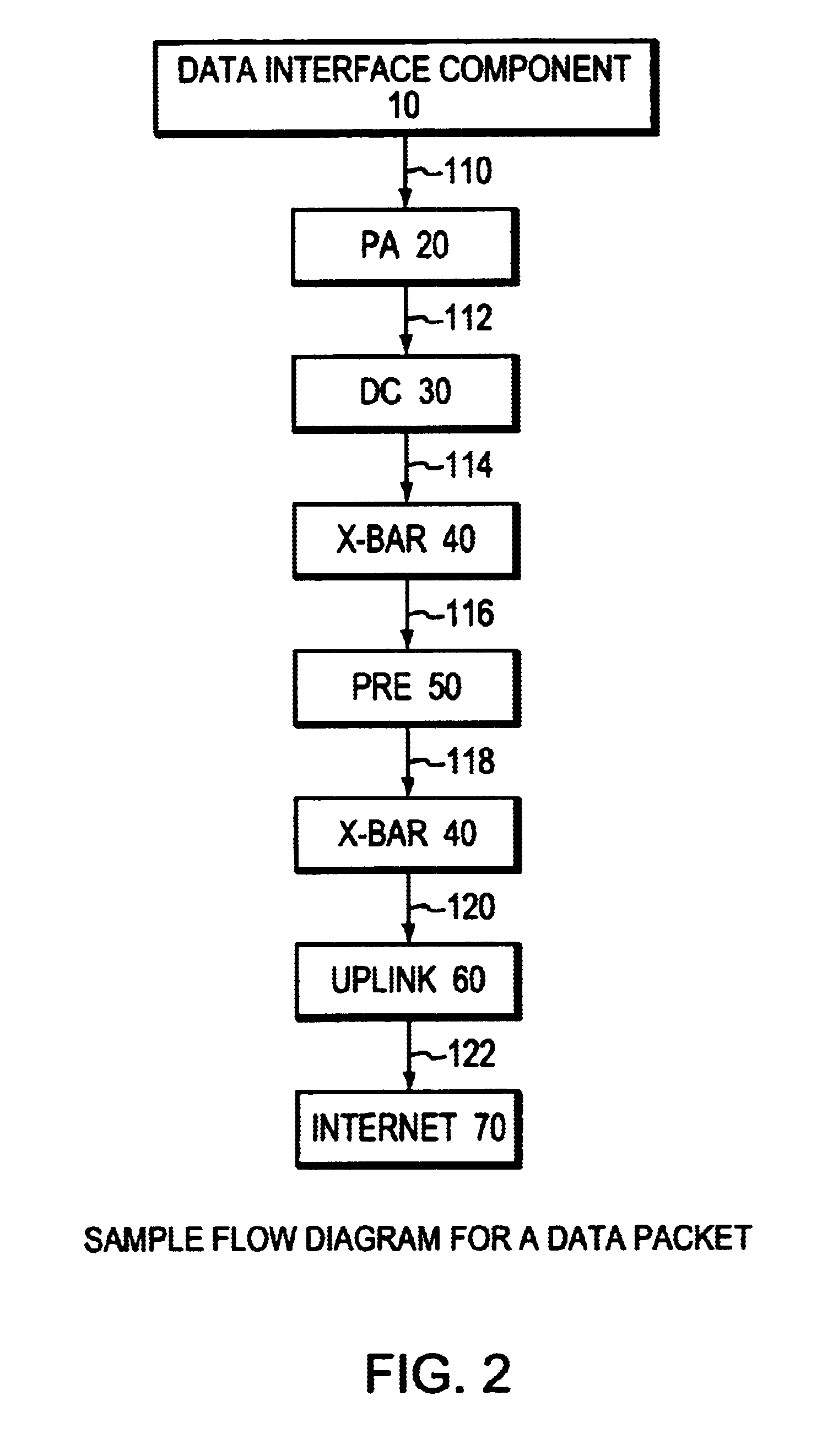
[0017]FIG. 2 shows a sample flow diagram for a data packet.

[0018]FIG. 3a shows an example port adapter design for an Ethernet interface.

[0019]FIG. 3b shows an example port adapter design for a channelized T3 line (CT3) interface.

[0020]FIG. 4 shows an example Data Compiler.

[0021]FIG. 5 shows an example packet digest format.

DETAILED DESCRIPTION OF A PREFERRED EMBODIMENT

[0022]In the following description, a preferred embodiment of the invention is described with regard to preferred process steps and data structures. However, those skilled in the art would recognize, after perusal of this application, that embodiments of the invention may be implemented using a set of general purpose computers operating under program control, and that modification of a set of general purpose c...


PUM


Abstract

The invention provides a router architecture that is scalable, that is, as more processing power is desired, more individual processors can be added. The data flow from each line can be distributed among all of the processors in the system. As desired services are added, increasing the amount of “touch” or processing performed on the packets in the system, more processors can be added to carry the increased load. The router architecture is also able to distribute the high interface rate of an uplink connection in the same manner. Packets are allocated to processors in a manner that allows the original order of data packets within the same flow to be maintained. The system uses a hash function to distribute the flows, making sure that packets within the same flow are sent to the same processor so that the original packet order in each flow is maintained. Different flows may be sent to different processors.

Description

CROSS-REFERENCE TO RELATED APPLICATION[0002]The subject matter of the subject application is related to that in copending U.S. Patent Application Ser. No. 09 / 62 1,415 filed Jul. 21, 2000, entitled “Load Sharing Across Flows.”BACKGROUND OF THE INVENTION[0003]1. Field of the Invention[0004]The present invention relates to architecture for a router. More particularly, the present invention relates to architecture for a router with scalable processing power.[0005]2. The Prior Art[0006]Computers generate and utilize large amounts of data. Different components in a computer network, for example, several different computers each with an internet connection or “uplink”, need to be linked together to allow for the transfer of data among the different components in the network. Routers perform this function. Routers take data input from one component in a network and ensure that it is properly transferred to another component in the network.[0007]Different components in a computer network may...

Claims


Application Information

Patent Timeline
Patent Type & Authority Patents(United States)
IPC IPC(8): H04L12/56H04L12/801H04L12/851
CPCH04L47/2441H04L47/10
Inventor COHEN, EARL
Owner CISCO TECH INC
Learn More