Mask pattern correction method, mask pattern creation system using the correction method, and computer-readable recording medium

a mask pattern and correction method technology, applied in the field of mask pattern correction method, mask pattern creation system using the correction method, computer-readable recording medium, can solve the problems of difficult to obtain high correction precision and very long correction time, and achieve the effect of short correction time, long correction time and high correction precision

Inactive Publication Date: 2005-02-08
KK TOSHIBA
View PDF7 Cites 23 Cited by
  • Summary
  • Abstract
  • Description
  • Claims
  • Application Information

AI Technical Summary

Benefits of technology

As described above, correction of the optical proximity effect by the conventional rule-based scheme requires only a short correction time, but is difficult to obtain a high correction precision. To the contrary, correction of the optical proximity effect by the simulation-based scheme can achieve high-precision correction, but takes a very long correction time.

Problems solved by technology

As described above, correction of the optical proximity effect by the conventional rule-based scheme requires only a short correction time, but is difficult to obtain a high correction precision.
To the contrary, correction of the optical proximity effect by the simulation-based scheme can achieve high-precision correction, but takes a very long correction time.

Method used


Image

  • Mask pattern correction method, mask pattern creation system using the correction method, and computer-readable recording medium
  • Mask pattern correction method, mask pattern creation system using the correction method, and computer-readable recording medium
  • Mask pattern correction method, mask pattern creation system using the correction method, and computer-readable recording medium

Examples


first embodiment

[First Embodiment]

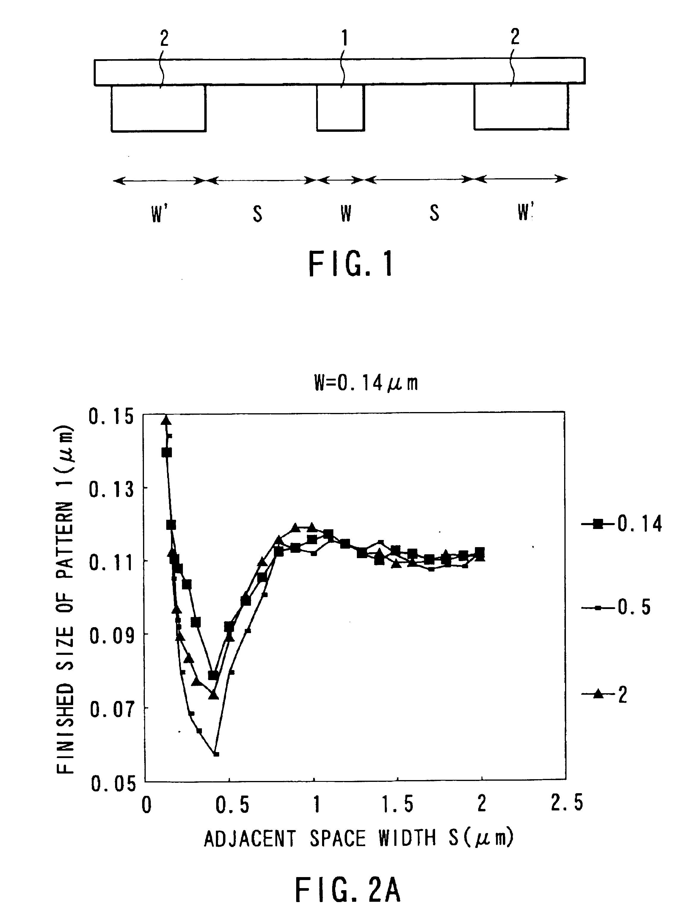
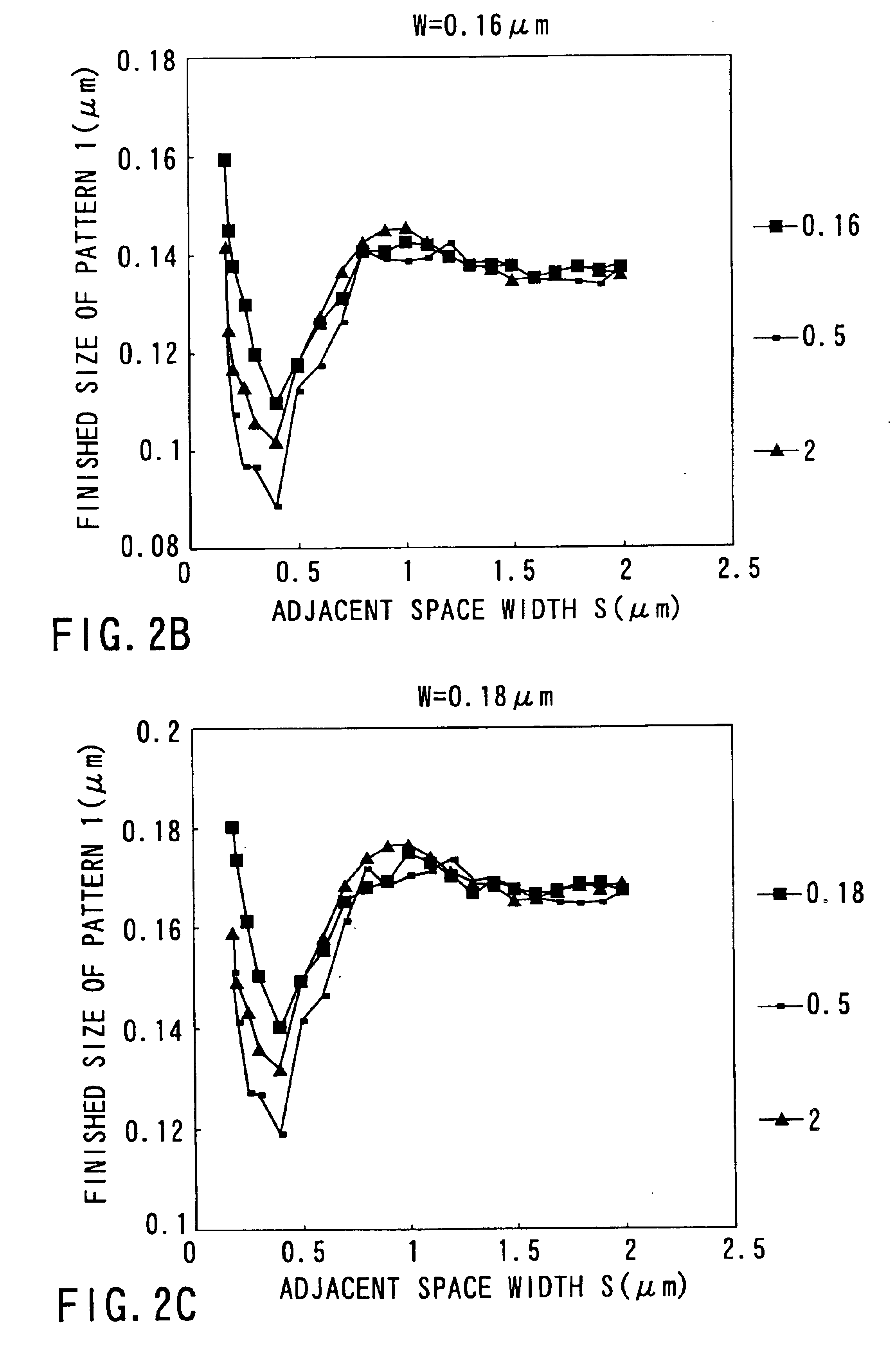
A one-dimensional pattern shown in FIG. 1 was used to calculate the finished size of a pattern when a line width W of a correction target pattern 1, a space width S to the edge of an adjacent pattern 2, and a line width W′ of the adjacent pattern, which are main factors influencing the finished size of the correction target pattern 1, were changed. Exposure conditions were λ=0.248 μm, NA=0.68, σ=0.75, ε=0.67, and a 6%-HT bright-field mask. Masks having W=0.14 to 0.25 μm, S=W to 2.0 μm, and W′=W to 2.0 μm were formed. The light intensity was calculated for each mask. To consider the influence of the resist developing process, the Gaussian function was convoluted in each calculated optical image. The finished size was calculated from the resultant image.

FIGS. 2A to 2C show the finished size of a pattern when S and W are changed for each line width W of the correction target pattern. As is apparent from FIGS. 2A to 2C, the finish pattern size changes depending on not ...

second embodiment

[Second Embodiment]

A critical value S′ of the adjacent space width S assigned to the simulation- or rule-based scheme was calculated on the basis of the results of the first embodiment.

Assuming that the minimum moving amount of a correction target edge that is determined by execution / non-execution of mask inspection, the allowance of the mask data amount, and the like is 5 nm, and MEF (Mask Enhanced Factor) is 1 to 2, the finished size suffers a size error of about 5 nm×2 (number of edges)×MEF=about 10 to 20 nm. At this time, the size error amount cannot be decreased unless the minimum edge moving amount is decreased. Note that MEF is the change amount (nm) of the finished size on a wafer when the mask changes by 1 nm.

As is apparent from FIGS. 3A to 3C, the change amount of the finished size depending on the adjacent pattern line width W′ is about 10 nm for an adjacent space width S of 0.8 μm or more. Also when masks were a Cr mask and dark-field mask, the same calculation as in the...

third embodiment

[Third Embodiment]

Correction of a two-dimensional pattern shown in FIG. 4 will be explained. A correction target pattern 21 is corrected in consideration of a pattern 22 nearest in a direction perpendicular to the direction of length of the correction target pattern 21, and a pattern 23 nearest in the direction of length of the correction target pattern 21.

The third embodiment calculated shortening amounts when adjacent pattern space widths sp and sh between the correction target pattern 21 and the patterns 22 and 23 adjacent to this correction target pattern, and line widths wp and wh of the adjacent patterns 22 and 23 changed, and checked the change amounts of the shortening amounts particularly when the line widths wp and wh of the patterns 22 and 23 changed. In this case, the shortening amount is defined as a retreat amount from the end of a finished pattern calculated from the correction target pattern 21, and a positive shortening amount means retreat.

When the shortening amoun...


PUM

PropertyMeasurementUnit
widthaaaaaaaaaa
widthaaaaaaaaaa
sizeaaaaaaaaaa

Abstract

A mask pattern correction method includes the step of extracting a correction target edge from a design pattern, the step of calculating the distance from the correction target edge to the nearest edge of an adjacent pattern, the step of calculating the correction value by a simulation in accordance with a pattern layout present within a given range determined by the correction target edge, and moving the correction target edge on the basis of the calculated correction value when the distance calculated in the distance calculation step is smaller than a predetermined distance, and the step of moving the correction target edge on the basis of an correction value set as a rule in advance in accordance with the distance when the distance calculated in the distance calculation step is larger than the predetermined distance.

Description

CROSS-REFERENCE TO RELATED APPLICATIONSThis application is based upon and claims the benefit of priority from the prior Japanese Patent Application No. 11-375477, filed Dec. 28, 1999, the entire contents of which are incorporated herein by reference.BACKGROUND OF THE INVENTIONThe present invention relates to a mask pattern correction method for forming a desired pattern on a wafer, a mask pattern creation system using the correction method, and a computer-readable recording medium.The advance of recent semiconductor manufacturing techniques is remarkable, and semiconductors 0.20 μm in minimum processing size can be manufactured. This miniaturization is realized by rapid progress of a micro-pattern formation technique called photolithography. Photolithography includes a series of steps of creating a mask from an LSI design pattern, irradiating the mask with light, exposing a resist applied to a wafer to light in accordance with a pattern drawn on the mask by a projection optical syst...

Claims


Application Information

Patent Timeline
Patent Type & Authority Patents(United States)
IPC IPC(8): G03F7/20G03F1/14H01L21/027G03F1/36G03F1/68
CPCG03F7/70441G03F1/144
Inventor KOTANI, TOSHIYATANAKA, SATOSHIINOUE, SOICHI
Owner KK TOSHIBA
Why Eureka
Try Eureka