Porous membrane structure and method

a porous membrane and membrane technology, applied in the field of porous membranes, can solve the problems of requiring relatively expensive equipment and materials, unable to effectively resist liquid penetration of membranes, and unable to freely permeate through polyurethane layers,

Inactive Publication Date: 2005-02-15
BHA ALTAIR
View PDF29 Cites 76 Cited by
  • Summary
  • Abstract
  • Description
  • Claims
  • Application Information

AI Technical Summary

Problems solved by technology

However, the ePTFE membrane tends to absorb oils and certain contaminating agents, such as body oils contained in perspiration, fatty substances or detergent-like contaminants.
When the ePTFE membrane becomes contaminated by absorbing the oils or other contaminating agents, the membrane may no longer effectively resist liquid penetration.
However, air may not freely permeate through the polyurethane layer.
However, this approach requires relatively expensive equipment and materials, such as an ultraviolet curing station and a nearly oxygen-free or inert atmosphere, to process and polymerize the monomer once it is applied to the membrane.
Furthermore, this approach requires solvents, cross-linking reactants and / or initiators that may be environmentally unsound and difficult to obtain.
A relatively expensive fluorosurfactant is used in amounts that may be difficult to completely remove from the membrane in order to permit the polymer in the aqueous dispersion to enter the pores of the membrane.

Method used


Image

  • Porous membrane structure and method
  • Porous membrane structure and method
  • Porous membrane structure and method

Examples


example 1

MEMBRANE EXAMPLE 1

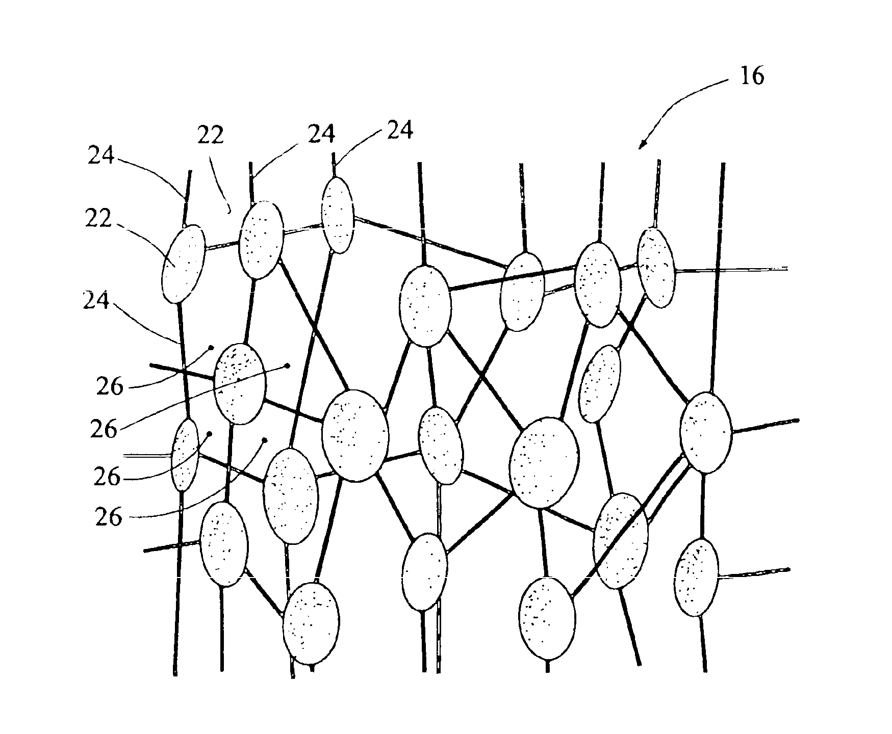
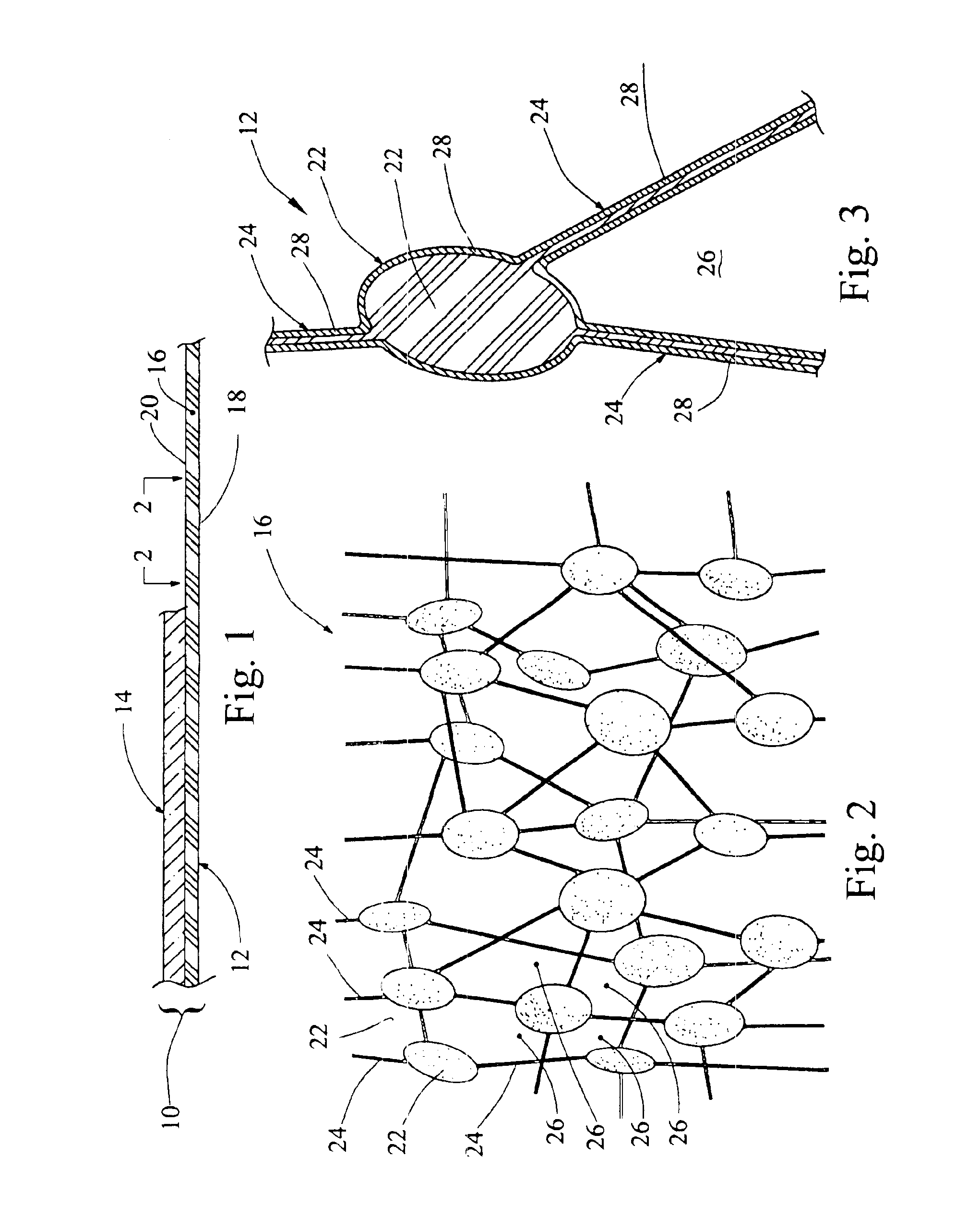
A microporous membrane 16 (manufactured by BHA Technologies, Inc. and designated QM011) made from ePTFE material was used. The membrane 16 preferably has an average pore size in the range of about 0.35 to 1.0 micron. The membrane 16 is preferably about 0.0015 inch thick. The membrane 16 is preferably at least partially sintered.

treatment example 1

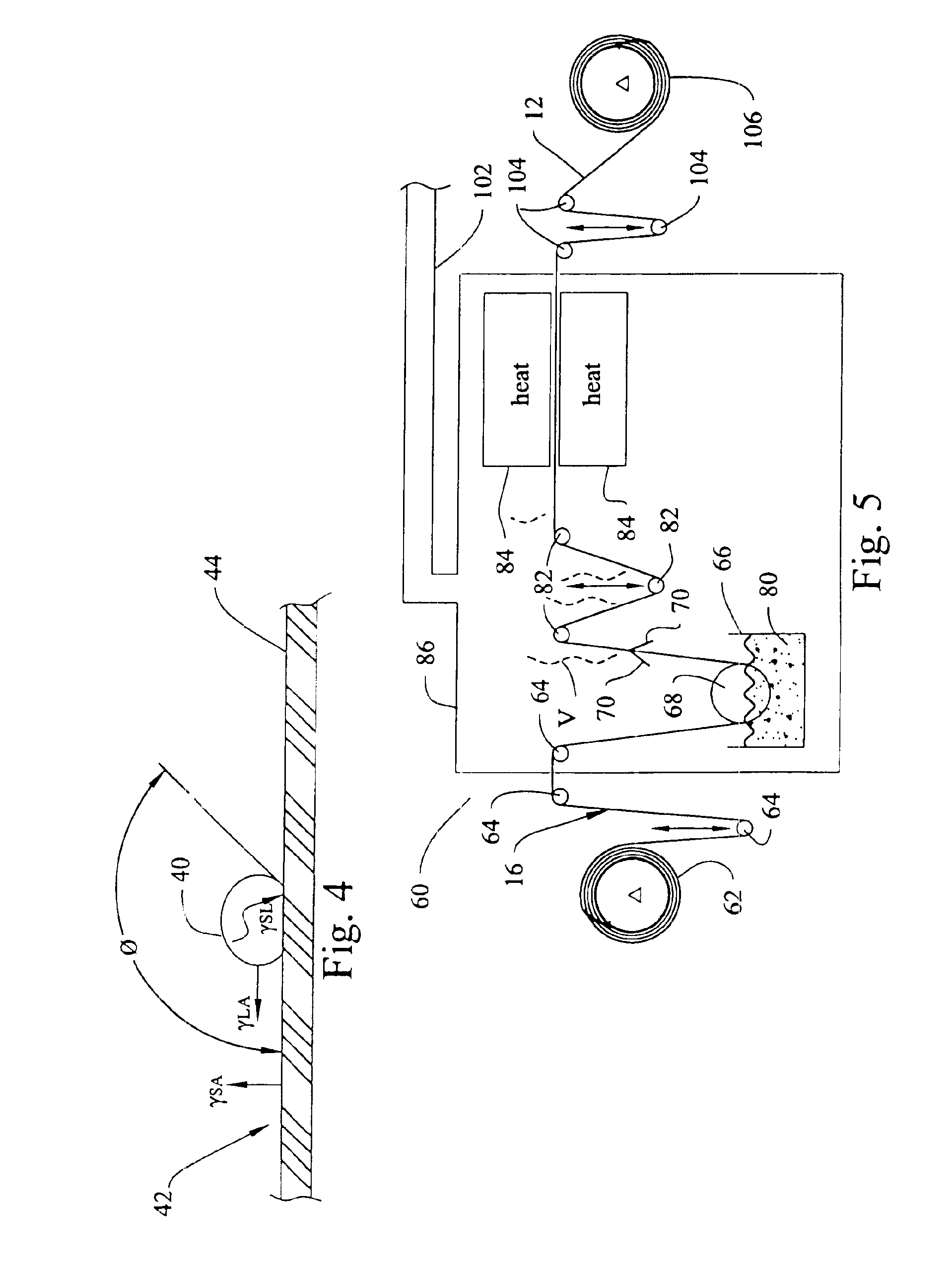
The membrane 16 described above was treated with a diluted and stabilized Zonyl® 7040 dispersion. The following diluted and stabilized dispersion was used for treatment:

treatment componentpercent by weightoleophobic fluoropolymer dispersion (Zonyl ® 7040)13.9stabilizing agent (water)21.5wetting or diluting agent (IPA)64.6

The samples were heated to between 220° C. and 240° C. for thirty seconds to coalesce the solids onto the nodes and fibrils of the treated membranes. Over three hundred treated membranes were tested. Most of the pores in the treated membranes were not “blinded” or closed off. All the treated membranes displayed air permeabilities of more than 0.1 CFM / ft2 and most were in the range of 0.2 and 1.3 CFM / ft2. All the treated membranes displayed an MVTR of more than 69,000 gr / m2 / day and most were in the range of 70,000 and 102,000 gr / m2 / day. The treated membranes would hold out at least an 80% IPA challenge.

It is important to remember that comfort of the user of the compo...


PUM

PropertyMeasurementUnit
temperatureaaaaaaaaaa
contact angleaaaaaaaaaa

Abstract

A method of treating a membrane comprises the steps of providing a membrane with surfaces that define a plurality of pores extending through the membrane. Providing a dispersion of oleophobic fluoropolymer solids. Stabilizing the dispersion with a stabilizing agent. Diluting the dispersion with a wetting agent. Wetting surfaces which define the pores in the membrane with the diluted and stabilized dispersion. Removing the wetting agent and the stabilizing agent from the membrane. Coalescing the oleophobic fluoropolymer solids of the dispersion on surfaces that define pores in the membrane. A composite membrane comprises a porous membrane having a plurality of interconnecting pores extending through the membrane and made from a material which tends to absorb oils and certain contaminating surfactants. A coating is disposed on surfaces of the nodes and fibrils defining the interconnecting passages in the membrane. The coating comprises oleophobic fluoropolymer solids coalesced on surfaces of the nodes and fibrils to provide oil and surfactant resistance to the composite membrane without completely blocking pores in the membrane. The composite membrane is gas permeable, liquid penetration resistant and capable of moisture vapor transmission at a rate of at least 70,000 gr / m2 day.

Description

STATEMENT REGARDING FEDERALLY SPONSORED RESEARCH OR DEVELOPMENTNot Applicable.BACKGROUND OF THE INVENTION1. Field of the InventionThe present invention relates generally to a composite membrane and a method of making the composite membrane. In particular, the present invention relates to a porous membrane that is treated to provide oleophobic properties to the membrane and to a method of treating the membrane.2. Description of Related ArtIt is known that technical fabrics must be suitable for use in demanding applications. Examples of such demanding applications include filter elements, outerwear garments and apparel, footwear, tents, sleeping bags, protective garments, clean room garments, surgical drapes, surgical gowns, other types of barrier wear and allergen barrier products. The technical fabrics often include a film or membrane to protect the fabric user from an external condition or environment and / or protect the external environment from contamination by the user. The film ...

Claims


Application Information

Patent Timeline
Patent Type & Authority Patents(United States)
IPC IPC(8): B01D67/00B01D69/00B01D69/12B01D71/00B01D71/36D06M15/21D06M15/277
CPCB01D67/0088B01D69/12D06M15/277B01D71/36D06M2101/22Y10T428/249955Y10T428/249991
Inventor KLARE, ROBERT JOHN
Owner BHA ALTAIR
Why Eureka
Try Eureka