
Conformable balloonless catheter

a balloonless catheter and balloon technology, applied in the direction of catheters, diaphragm valves, instruments, etc., can solve the problems of many problems of catheters, failure to overcome the problems of foley catheters, renal failure and death, etc., to achieve the effect of restoring more normal body function, reducing fluid pressure buildup, and reducing the risk of renal failur

Inactive Publication Date: 2005-02-15
FLINCHBAUGH DAVID E DR
View PDF18 Cites 187 Cited by
  • Summary
  • Abstract
  • Description
  • Claims
  • Application Information

AI Technical Summary

Benefits of technology

A secondary objective of the invention is to provide an indwelling catheter that does not require extra inflation lines for inflating a balloon end nor an inflatable portion.
The invention can be used as a hospital instrument whenever an indwelling catheter is required, or in clinics, or in physician's offices, or in homes for draining urine from bladders of patients automatically and safely after normal filling, thoroughly and antiseptically. This use is in strong contrast to the typical, non-cyclical, continuous drip associated with urethral catheter drainage into a collection bag. The use of the invention with catheterized patients can help some patients with bladder “retraining” to restore the more normal body function of bladder filling and emptying in a cyclic manner, with normal, healthy pressure sensations in spite of the presence of the catheter which here-to-fore prevented “natural” bladder drainage.

Problems solved by technology

A catheter can be a lifesaving tool since an uncontrolled buildup of urine can cause serious medical problems including renal(kidney) failure and death.
Although popular, these catheters have many problems.
Various types of catheters have been proposed but still fail to overcome the problems of the Foley Catheter.
Each of these patents generally require inflatable portions or retainers having similar problems.
Catheters have also been known to cause other types of problems.
Struvite crystals have sharp, jagged edges which can seriously lacerate the urethral lining when the conventional catheter is removed.
This bloody situation is not only excruciatingly painful but can lead to deadly infections.
A dynamic functioning system is converted to a static state with a catheter, and painful bladder spasms can occur.
These devices are subject to distortion by shifting and turning of the patient and are unreliable (can compromise safety) and restrict patients.
These types of devices, can be expensive, bulky and positions an electricity source close to the catheter and the patient.
A problem with this system was that the restoring force of the spring increased with distance of travel from a closed position.
The valve is unsatisfactory because it closed again as soon as the urine fluid pressure dropped off, thus causing fluid to remain trapped in the bladder to stagnate with further elapsed time.
Only a full bladder would open it, sometimes at an uncomfortably high (and potentially unsafe) pressure, and then it closed too soon to allow complete drainage unless overridden by the patient bearing down heavily on the lower abdomen.
These devices use components substantially larger than a standard diameter of a catheter, thus taking up more space, is more obtrusive, more labor intensive.
None of the proposed patented devices and techniques described above solve all the problems with catheters that are listed above.

Method used


Image

  • Conformable balloonless catheter
  • Conformable balloonless catheter
  • Conformable balloonless catheter

Examples


embodiment 200

Referring to FIGS. 19-20, magnetic valve embodiment 200 can include a pliable thin walled ring member 210, such as pliable plastic and the like, fixably attached to an inside wall portion 61 of the novel catheter tube 60. Attached to an extending downward from the ring member 210 can be funnel portions 220, 230 that can be formed from two thin pliable flaps having a lower end portions with small pliable type magnets 225, 235 attached thereto that be attracted to each other closing off the passageway formed from the opening through ring member 210 which can give the appearance of a funnel shape, and the like. Alternatively, the funnel portions 220, 230 can be single pliable cylindrical chamber such as thin walled plastic, a plastic bag, and the like, that can have a wall thickness of approximately 0.001 inches, and the like. Although two magnets 125, 135 are described, the invention can be used with one magnet 125 and a portion 135 having metal attributes and the like. Similar to the...

embodiment 300

FIG. 21 is a cross-sectional view of an electret cycling valve embodiment 300 in a closed position within a catheter 60 for controlling bladder drainage. FIG. 22 is another view of the valve 301 of FIG. 21 in an open position. Here a pliable thin walled ring member 310 can be fixably attached to an inner wall surface 61 of catheter tube 60. Extending below ring member 310 can be two electret material sheets 320, 330 such as flexible plastic sheets imbedded with electric charges. For example, sheet 320 can include a positive charge on the inner surface of lower end 322 and sheet 330 can include a negative charge an inner surface of lower end 332. Similar to the preceding embodiment the sheets 320, 330 can form a funnel shape that can open and close the passageway formed by inner walls 61 of the catheter tube 60. The electret attraction of the portions 322, 332 of the funnel portions 320, 330 can be calibrated to be approximately equal to natural bladder drainage pressure flows. For e...

embodiment 400

Embodiment 400 can use the urocycler components described in parent U.S. application Ser. No. 10 / 010,534 filed Dec. 7, 2001, which is incorporated by reference, and can include inlet barbed connector 402 and outlet barbed connector 404 attached to opposite ends of main nonmagnetic housing 420, the latter of which can have a male pronged end 424 which snapably and sealingly attaches to a female prong end 422. A vent hole port 426 can be located on the downstream end of male housing portion 424. Inside the upstream portion 422 of housing 420 can be a fixed valve member 432 being formed of a magnetic member, and the like, fixed in position adjacent to a hollow valve port ring 434 whose center flow passageway can be opened and closed by moveable valve member 438 with resilient valve seat 436 which can move forward and backward in the direction of double arrow MG along inner channel rails 439 so as to open and close the valve in a cycling manner similar to those embodiments previously de...


PUM


Abstract

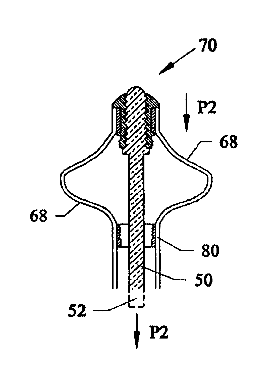
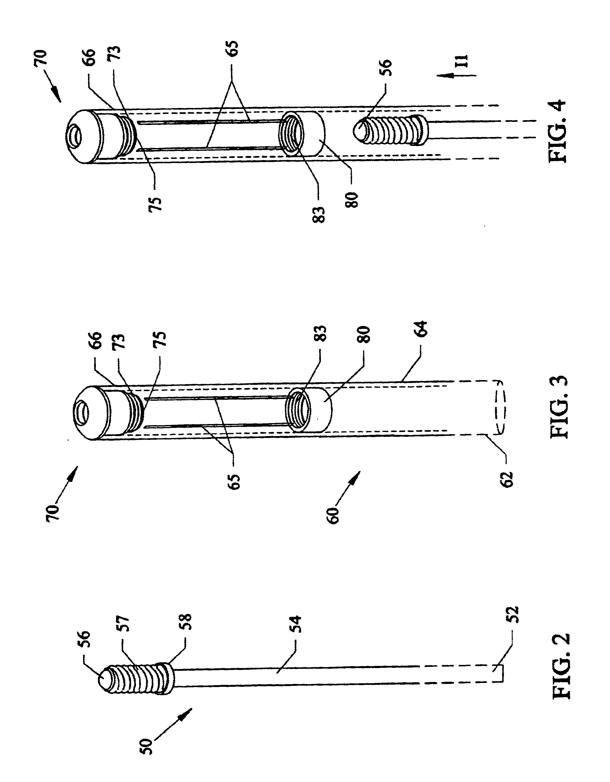
Indwelling catheter having an upper distal end having a portion that can expand within a bladder type spaces without having to be inflated. An embodiment allows for at least one slit on an upper side of the catheter tube and a head member that when pulled down by a stylette moving inside the catheter causes a bulge wing portion(s) that holds the catheter safely and painlessly within the bladder. Magnetic and electret valves can be included inside the tube of the catheter that can cycle between open and closed positions when activated by normal bladder pressure when urination is desired. The novel catheter tube can naturally conform to an opening and closing urethra during natural bladder drainage. The catheter tube surface can include an anti-microbial layer that is either or both coated and impregnated thereon with either an antibacterial and / or hydrophyllic materials. Sampling ports can be located on both inside catheter tube valves and on an externally attached magnetic valve.

Description

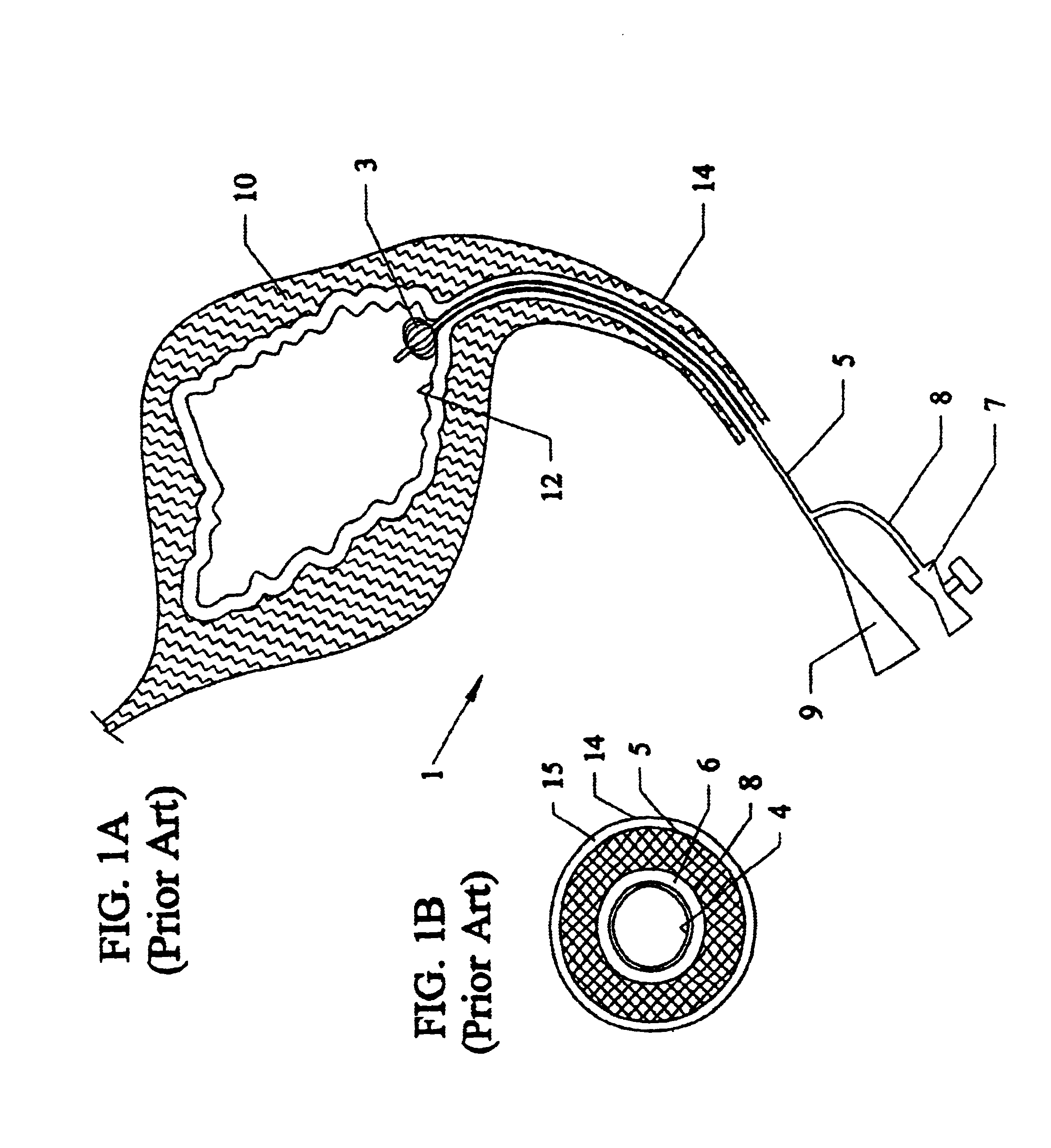
BACKGROUND AND PRIOR ARTCatheters are often used for performing continuous bladder irrigation. The most popular type of catheter used is a Foley indwelling or retention catheter that uses an inflatable balloon at the end being inserted into the bladder. See for example, U.S. Pat. No. 4,335,723 to Patel. For the Foley catheter a separate inflation tube adjacent to the main catheter tube or circumferential about the main catheter tube is used to inflate the balloon portion inside the bladder.Urinary catheters bypass the normal bladder process of storing urine, and for releasing the urine by using the bladder detrusor muscle. Catheters can be a necessary tool to open the bladder to allow urination when patients have trouble urinating. A catheter can be a lifesaving tool since an uncontrolled buildup of urine can cause serious medical problems including renal(kidney) failure and death.FIG. 1A shows a prior art indwelling Foley type catheter 1 with a balloon tipped end 3 adjacent to an i...

Claims


Application Information

Patent Timeline
IPC IPC(8): A61M25/02A61M25/04A61M25/00A61M5/168F16K31/04F16K37/00F16K7/00F16K7/06A61F5/44A61M39/10
CPCA61F5/4405A61M25/0075A61M25/04A61M39/10A61M2210/1089A61M2025/0078A61M2025/0233A61M2210/1085A61M2025/0056
Inventor FLINCHBAUGH, DAVID E.
Owner FLINCHBAUGH DAVID E DR
Learn More