The present invention has a plurality of blade assemblies that are installed over the same axis. When subjected to natural wind velocity, these blade assemblies rotate to drive a power generator. The blade assemblies are arranged in the front-to-rear direction in such a manner that they overlap with each other. When the front and rear blade assemblies within this configuration catch the wind and rotate, the rear blade assembly rotates as it catches the wind generated by the rotating front blade assembly in addition to the wind coming from the front. Particularly, the ends of the blades of the front blade assembly rotate at high
peripheral velocity. Therefore, the wind blown rearward-from these ends has high wind velocity. The rear blade assembly is subjected to such high wind velocity so that blade assembly rotation takes place with high efficiency. Further, when the front blade assembly rotates, the natural wind blowing toward the front blade assembly is pushed outward due to rectification. Therefore, the wind caught by the rear blade assembly is conditioned better the wind that is caught by the front blade assembly. The rear blade assembly catches the rectified wind and can use the wind velocity efficiently. As a result, blade assembly rotation takes place with high efficiency.
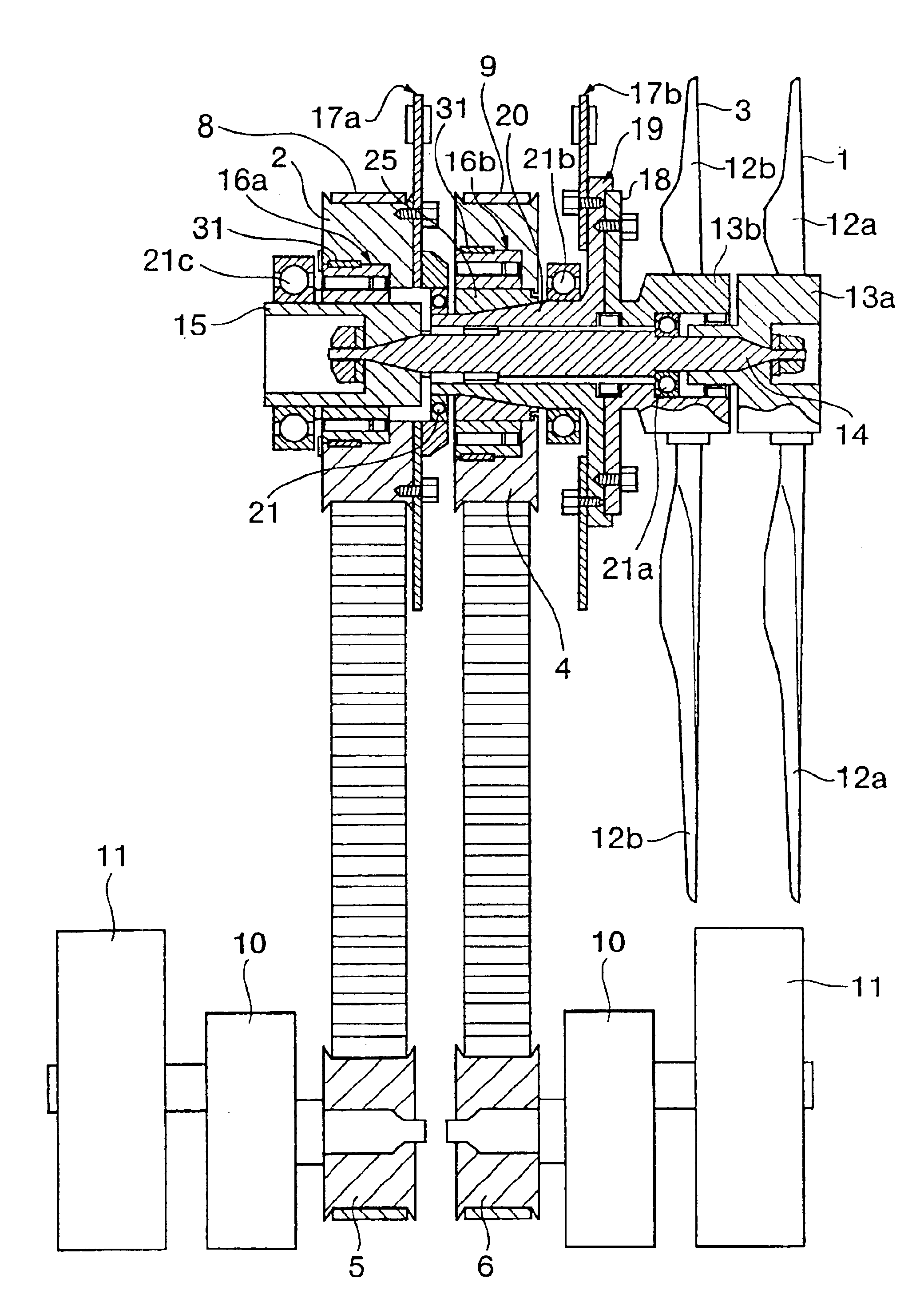
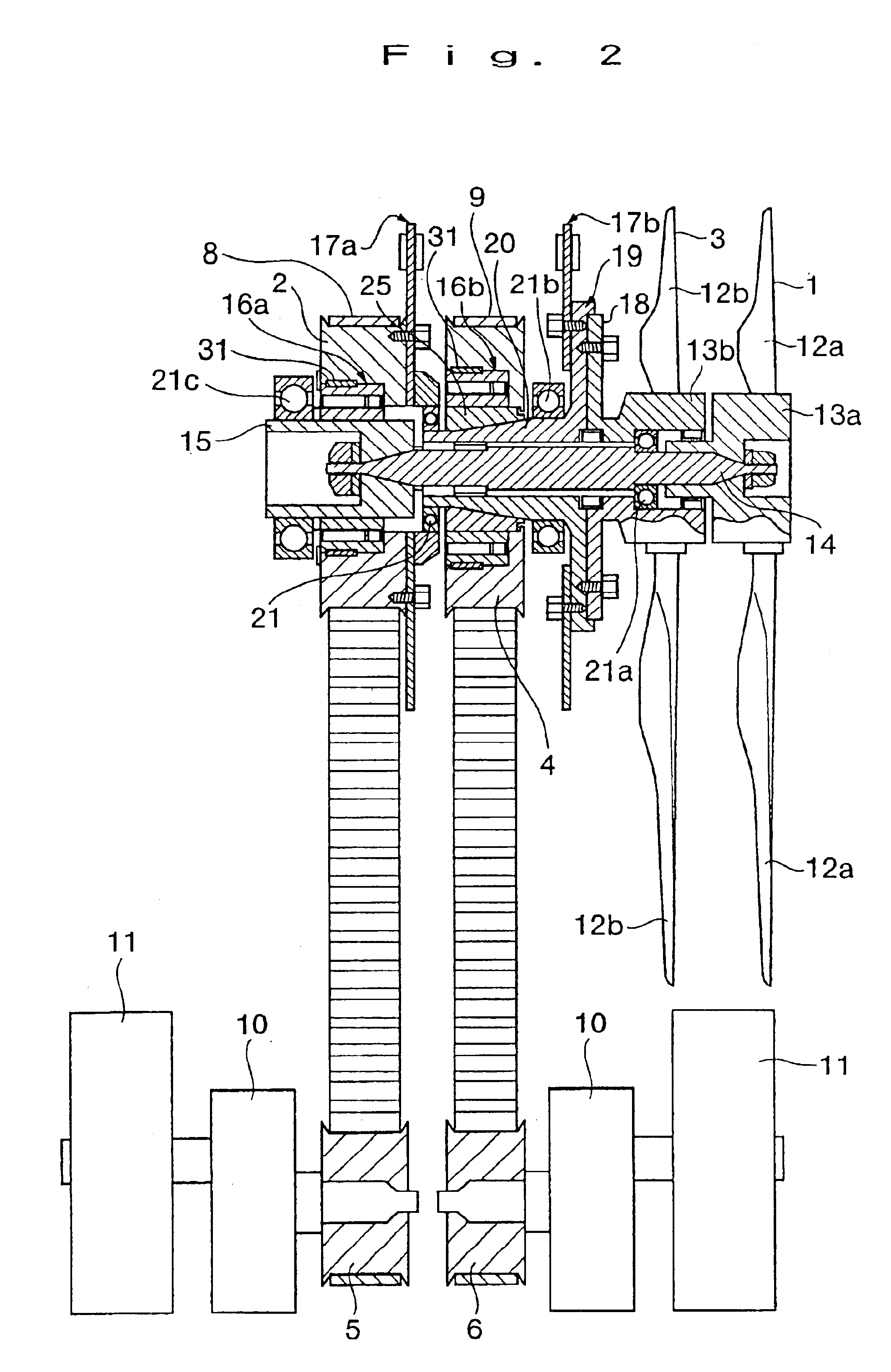
The wind turbine generator of the present invention comprises a power generator; a first blade assembly for being subjected to natural wind velocity to rotate and drive the power generator; a second blade assembly that is positioned behind the first blade assembly to overlap with the first blade assembly and subjected to the natural wind velocity to rotate for driving the power generator; and clutching means that are positioned between the first / second blade assemblies and the power generator to disengage the power generator from the first blade assembly and / or the second blade assembly to reduce the rotary load on the power generator when the first and second blade assemblies are loaded. When the first and second blade assemblies both catch the wind to rotate in a situation where the above configuration is employed, the second blade assembly, which is positioned rearward, rotates as it catches the wind generated by the rotating first blade assembly, which is positioned forward, in addition to the wind coming from the front. This results in an increase in the blade assembly rotation efficiency. If the wind velocity lowers to reduce the blade assembly rotating speed, the
power transmission line between the blade assemblies and power generator disconnects so that the power generator can rotate for a long period of time while the rotary load is reduced for the power generator only. If, in the meantime, the wind velocity increases to raise the blade assembly rotating speed, the
clutch locks so as to reconnect the
power transmission line between the blade assemblies and power generator. Therefore, the blade assemblies accelerate the power generator and impart
high torque to rotate it. As a result, the power generator can be efficiently driven.
The wind turbine generator of the present invention is configured so as to use a one-way
clutch as clutching means. This
clutch engages when the first blade assembly and / or the second blade assembly are about to rotate faster than the power generator. The use of this configuration makes it possible to automatically detect blade assembly rotation and control the clutching means.
Further, the wind turbine generator of the present invention is configured so that a plurality of blade assemblies, which catch the natural wind to rotate and drive the power generator, are installed over the same axis and arranged in the front-to-rear direction in an overlapping manner. More precisely, the blades of the blade assemblies are constantly positioned so that their angular positions do not coincide with each other. When the front and rear blade assemblies catch the wind to rotate within this configuration, the rear blade assembly rotates as it catches not only the wind coming from the front but also the wind generated by the front blade assembly which is rotating. Particularly, the ends of the blades of the front blade assembly rotate at high
peripheral velocity. Therefore, the wind blown rearward from these ends has high wind velocity. The rear blade assembly is subjected to such high wind velocity so that blade assembly rotation takes place with high efficiency. Further, the relative rotary positions of the blades of front and rear blade assemblies are maintained within a predetermined
angular range so that they do not coincide with each other during blade assembly rotation in the rotating direction. Therefore, the amount of
wind noise generated by each blade assembly is reduced so that the resulting wind turbine generator generates a minimum of
noise. More specifically, the wind coming into contact with the blades of the front blade assembly and generating
wind noise is disturbed and deadened by the rotating blades of the rear blade assembly. Meanwhile, the wind coming into contact with the blades of the rear blade assembly is constantly disturbed by the rotating blades of the front blade assembly. Since the wind reaching the rear blade assembly is disturbed so as to reduce the strength of the wind, the amount of wind
noise generated by the rear blade assembly is reduced. As a result, the total amount of wind noise is minimized.
Furthermore, the wind turbine generator of the present invention is configured so as to employ a lock bearing that maintains the relative rotary positions of the blades of the first and second blade assemblies within a predetermined
angular range. When the first and second blade assemblies both catch the wind to rotate in this configuration, the second blade assembly, which is positioned rearward, rotates with higher efficiency that the first blade assembly. Therefore, when the second blade assembly attempts to rotate faster than the first blade assembly, the lock bearing works to keep the relative rotary positions of the blades of the first and second blade assemblies within a predetermined
angular range. This not only prevents the output torque from being attenuated by the
coincidence between the blades of the first and second blade assemblies, but also reduces the amount of wind noise. This results in a quiet wind turbine generator. In this configuration, the lock bearing prevents the blades of the first and second blade assemblies from coinciding with each other by keeping their relative rotary positions within a predetermined angular range. This configuration provides a quiet wind turbine generator in which the lock bearing maintains the relative rotary positions of the blades of the first and second blade assemblies within a predetermined angular range without allowing them to coinciding with each other. As an alternative method for preventing the blades of the first and second blade assemblies from coinciding with each other, magnets of the same polarity may be mounted respectively on the first and second blade assemblies and positioned so that they face each other when the blades of the first and second blade assemblies coincide with each other.
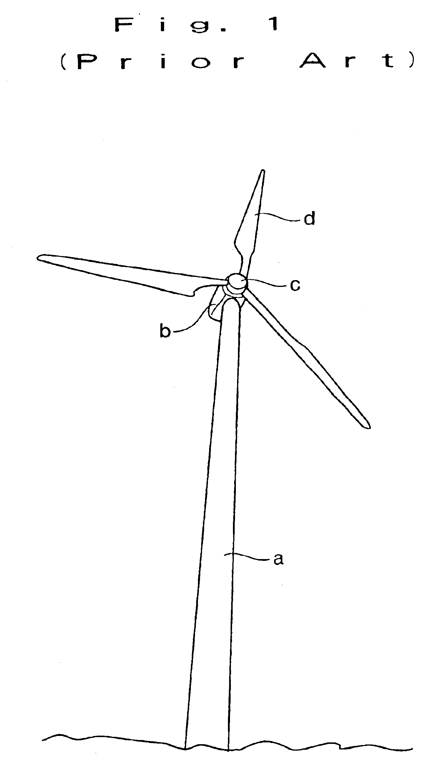
As described above, the wind turbine generator of the present invention has a plurality of blade assemblies that are installed over the same axis and arranged in the front-to-rear direction in an overlapping manner in order to catch the natural wind, rotate, and drive the power generator. This enables the wind turbine generator to obtain high blade assembly torque from wind velocity and generate electrical power with high efficiency. Consequently, the wind turbine generator of the present invention provides an extremely excellent
advantage. While the minimum wind velocity required for effective operations of conventional wind turbine generators is 5 m / s (5 meters per second), the wind turbine generator of the present invention effectively operates even when the wind velocity is as low as 3 m / s or so. When the frequency with which the wind velocity prevalent at a certain site (or in a certain area) is 5 m / s or higher is compared against the frequency with which the wind velocity is 3 m / s or higher, it is obvious that the latter frequency is much higher than the former one. Therefore, the abovementioned decrease in the minimum required wind velocity means a remarkable increase in the length of time during which the wind turbine generator operation is effective. It also indicates that the present invention makes it possible to install and operate an economically efficient wind turbine generator in any regions of the world where the wind blows (the wind velocity need not be high).

