Compact, low profile, single feed, multi-band, printed antenna

a low-profile, printed antenna technology, applied in the field of radio communication, can solve the problems of difficult to provide a multi-band pifa that has the requisite bandwidth and gain, negative impact on both the bandwidth and the gain of the pifa, and the geometric configuration imposed by the design of a ground plane for such a pifa that includes the pbg phenomenon, etc., to achieve satisfactory gain and bandwidth, low profile, cost-effective

Inactive Publication Date: 2005-02-15
LAIRDTECH INC
View PDF9 Cites 124 Cited by
  • Summary
  • Abstract
  • Description
  • Claims
  • Application Information

AI Technical Summary

Benefits of technology

An advantage of the present invention is that a physically compact, low profile, simple geometry, single-feed, planar and printed-antenna in accordance with the invention provides multi-band performance with satisfactory gain and bandwidth.
is that a physically compact, low profile, simple geometry, single-feed, planar and printed-antenna in accordance with the invention provides multi-band performance with satisfactory gain and bandwidth.
Structural configurations of various embodiments in accordance with this invention are cost-effective and easy to manufacture.
The requisite bandwidth performance of multi-band, planar and printed-antennas in accordance with this invention is realized without requiring the use of an impedance matching network that is external to the printed-antenna.
In spite of the constraints on an internal-antenna's geometry that is provided by the manufacturers of radio-devices such as cellular telephones, this invention provides viable printed-antenna embodiments that are physically compact, that provide for a single-feed, that are multi-band, and that provide satisfactory gain and bandwidth performance.
This invention provides embodiments of single-feed, multi-band, planar and printed-circuit antennas that are physically compact, and that have a low profile or height.

Problems solved by technology

A reduction in the physical volume that is available within the radio-device for housing the PIFA's radiating element results in a negative impact on both the bandwidth and the gain of the PIFA.
In addition, with a trend toward restricting the height of such internal-antennas to from about 3 millimeters (mm) to about 5 mm, it is difficult to provide a multi-band PIFA that has a requisite bandwidth and gain.
Although it may be that a PIFA design that is associated with a photonic band gap (PBG) structure can be used to overcome the negative effects of such a reduced height, the associated geometric configuration that is imposed by the design of a ground plane for such a PIFA that includes the PBG phenomenon is difficult.

Method used


Image

  • Compact, low profile, single feed, multi-band, printed antenna
  • Compact, low profile, single feed, multi-band, printed antenna
  • Compact, low profile, single feed, multi-band, printed antenna

Examples


Embodiment Construction

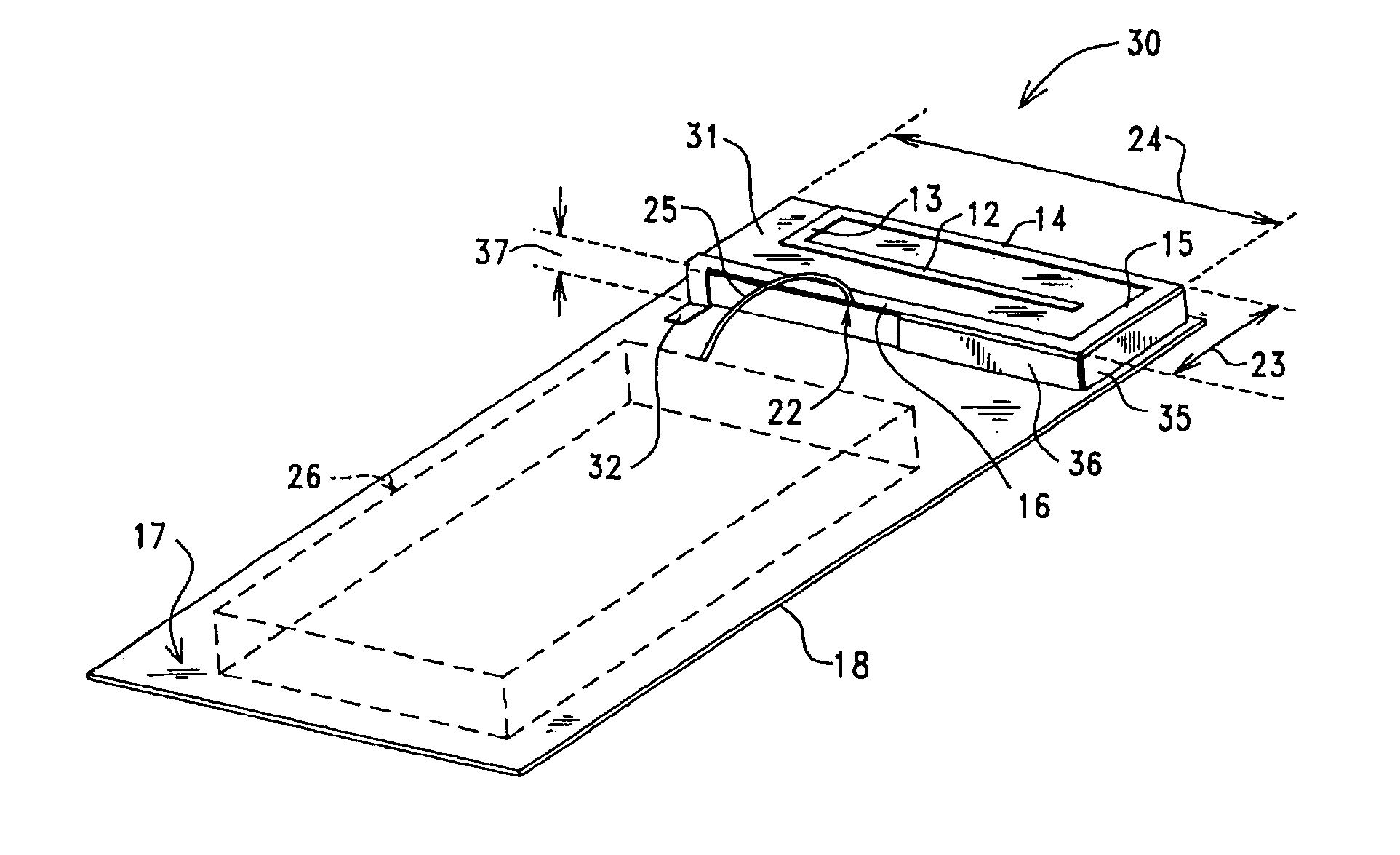
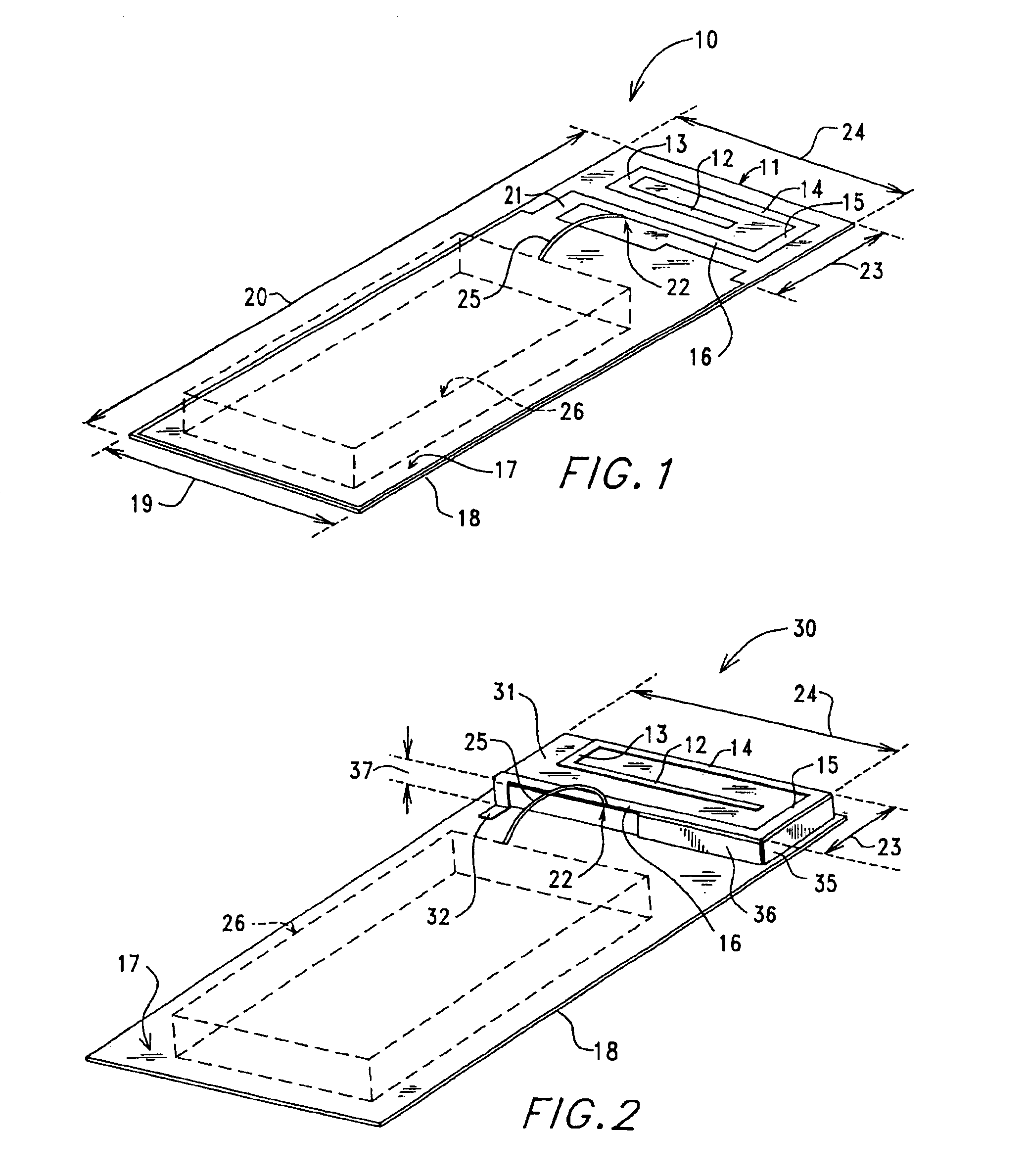
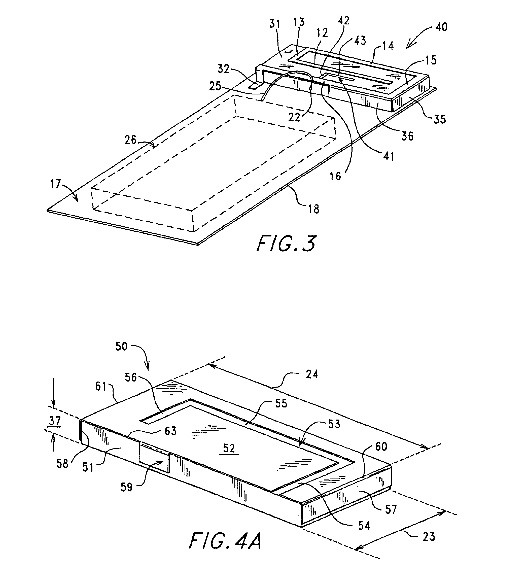
FIG. 1 is a top / side / end perspective view of a single-feed, two-band (GSM band and DCS band), printed-antenna 10 in accordance with the invention that is located in a small area on one end of PCB 18.

Reference numeral 17 identifies a flat, relatively large area and top-located metal surface of a PCB 18 that functions in a well known manner as a chassis within a radio-device such as a cellular telephone, wherein dimensions 19 and 20 generally correspond to the width and the length of a cellular telephone. Metal surface 17 may function as a ground-potential connection for components of a cellular telephone, wherein these components are represented by a dotted-box 26.

Antenna 10 includes a metal printed circuit radiating element 11 that is made up of five metal segments, i.e. inner segment 12, segment 13 that extends generally perpendicular from one end of segment 12, segment 14 that extends generally perpendicular from one end of segment 13, segment 15 that extends generally perpendicul...


PUM


Abstract

Printed circuit techniques and two-shot molding techniques are used to form a metal radiating element, a metal ground plane element, a metal antenna feed, a metal short-circuiting strip and metal capacitive loading plates within small antennas that are buried within transmit / receive radio-devices such a mobile cellular telephones. Balanced and unbalanced, single-feed, two and three band antennas are provided wherein the radiating element is laterally spaced from the ground plane element, to thereby provide an antenna having a very low profile or height, including antennas wherein the ground plane element and the radiating element are placed coplanar on the same surface of a PCB. A thin dielectric carriage on a PCB allows for the metal capacitive loading plates to be placed on the sidewalls of the dielectric carriage, to thereby provide reactive loading of a radiating element that is on the top surface of the dielectric carriage.

Description

FIELD OF THE INVENTIONThis invention relates to the field of radio communication, and more specifically to antennas for use with, or buried within, relatively small radio communication devices, of which mobile cellular telephones are a non-limiting example.BACKGROUND OF THE INVENTIONIn wireless voice and data communications systems, including mobile systems having multi-band and multi-system capabilities, reducing the physical size of the radio transmit / receive devices, such as mobile cellular telephones, is an important design consideration.For radiating / receiving antennas that are buried within the radio-devices (i.e. internal-antennas), the need to reduce the physical size of the radio-devices imposes a severe constraint on the physical volume within each radio-device that is allowed for an internal-antenna and its radiating / receiving element (hereafter called radiating element).A planar inverted-F antenna (PIFA) is commonly used as a radio-device's internal-antenna. A reduction ...

Claims


Application Information

Patent Timeline
Patent Type & Authority Patents(United States)
IPC IPC(8): H01Q1/38H01Q5/00H01Q9/04H01Q1/24H01Q5/357H01Q5/371
CPCH01Q1/243H01Q1/38H01Q5/371H01Q9/0442H01Q5/357H01Q9/0421H01Q1/24H01Q5/00H01Q13/08
Inventor KADAMBI, GOVIND RANGASWAMYYARASI, SRIPATHIHEBRON, THEODORE SAMUEL
Owner LAIRDTECH INC
Why Eureka
Try Eureka