Device and method for variable attenuation of an optical channel

Inactive Publication Date: 2005-02-15
BROADEX TECH UK LTD
View PDF11 Cites 9 Cited by
  • Summary
  • Abstract
  • Description
  • Claims
  • Application Information

AI Technical Summary

Benefits of technology

[0009]In accordance with an embodiment of the invention, a variable optical attenuator is provided having at least one elongated core, a cladding surrounding the core, and a controllable thermal source and a heat sink arranged on opposite sides of the core and defining therebetween a first or vertical axis oriented transversely to the longitudinal axis of the core. The core and cladding collectively form a conventional waveguide structure, which normally confines optical energy propagating along the longitudinal axis of the core by virtue of the difference in refractive indices between the

Problems solved by technology

The attenuators described in the foregoing references, as well as other prior art attenuators, are known to suffer from operationally significant problems or limitations.
These problems include sensitivity to ambient temperature, high power consumption, limited

Method used


Image

  • Device and method for variable attenuation of an optical channel
  • Device and method for variable attenuation of an optical channel
  • Device and method for variable attenuation of an optical channel

Examples


Embodiment Construction

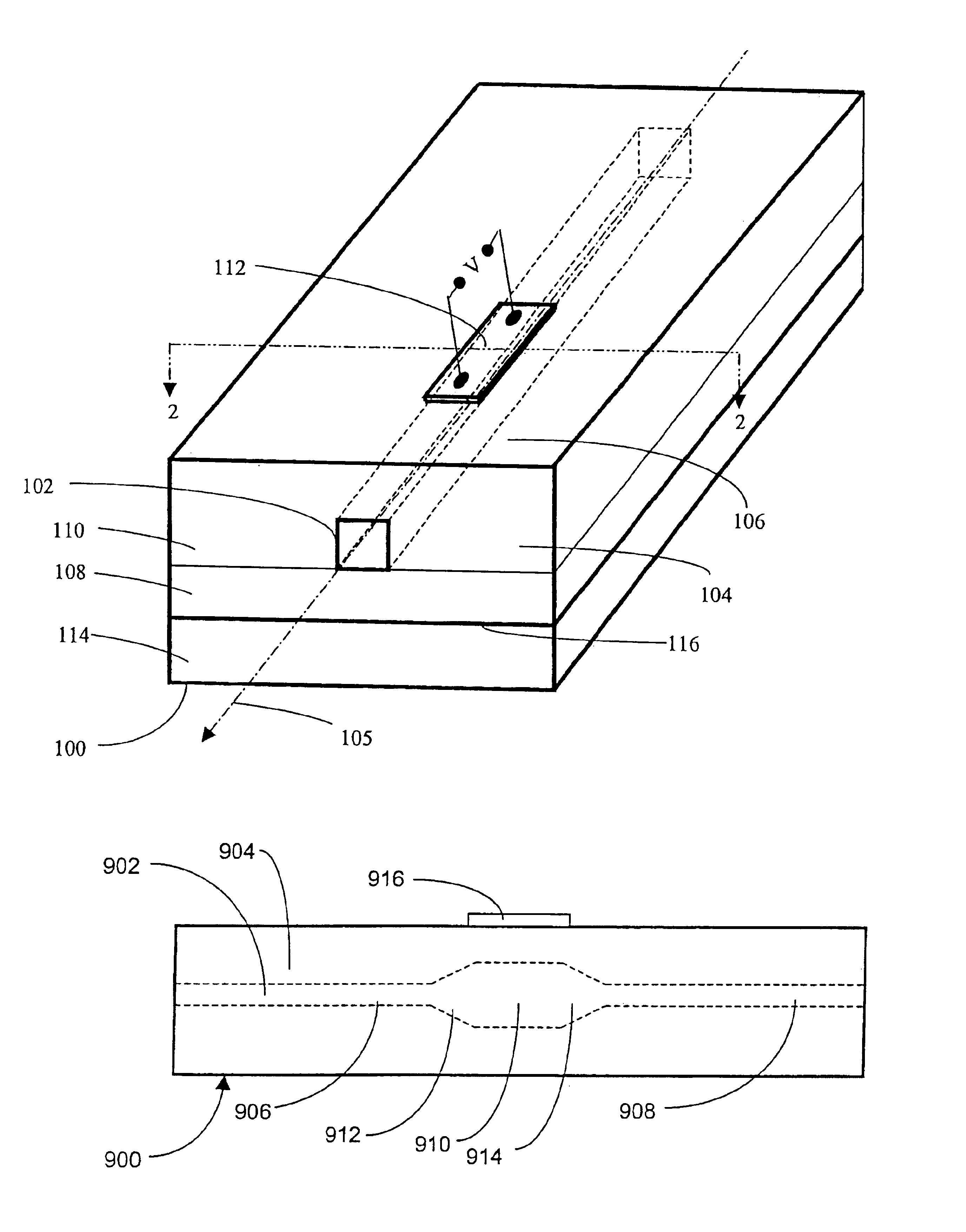
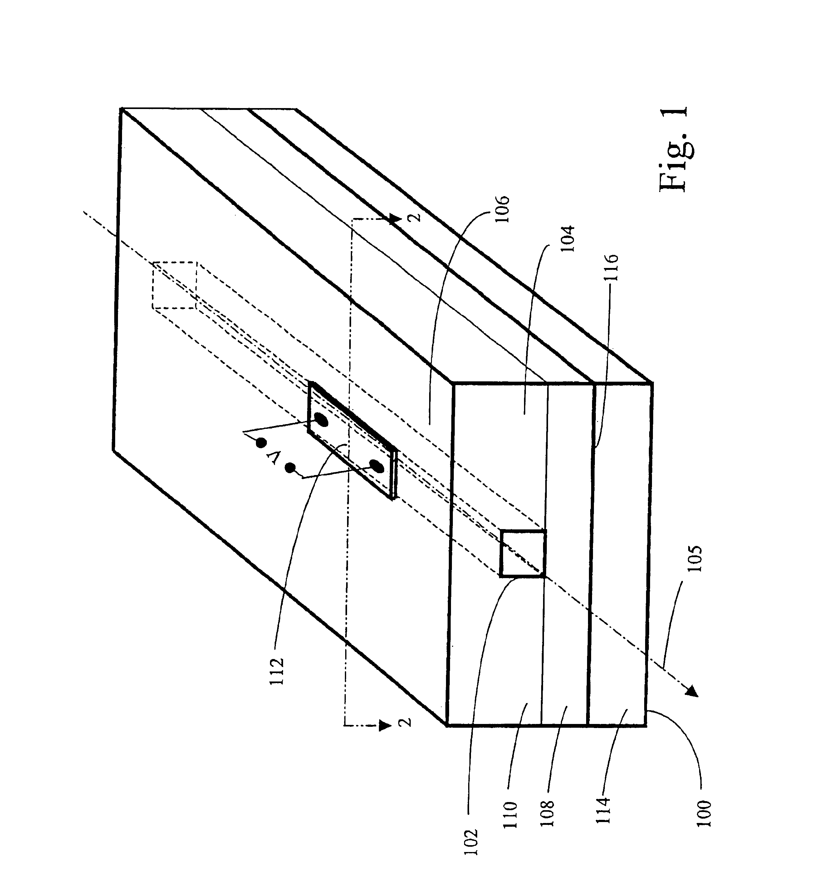
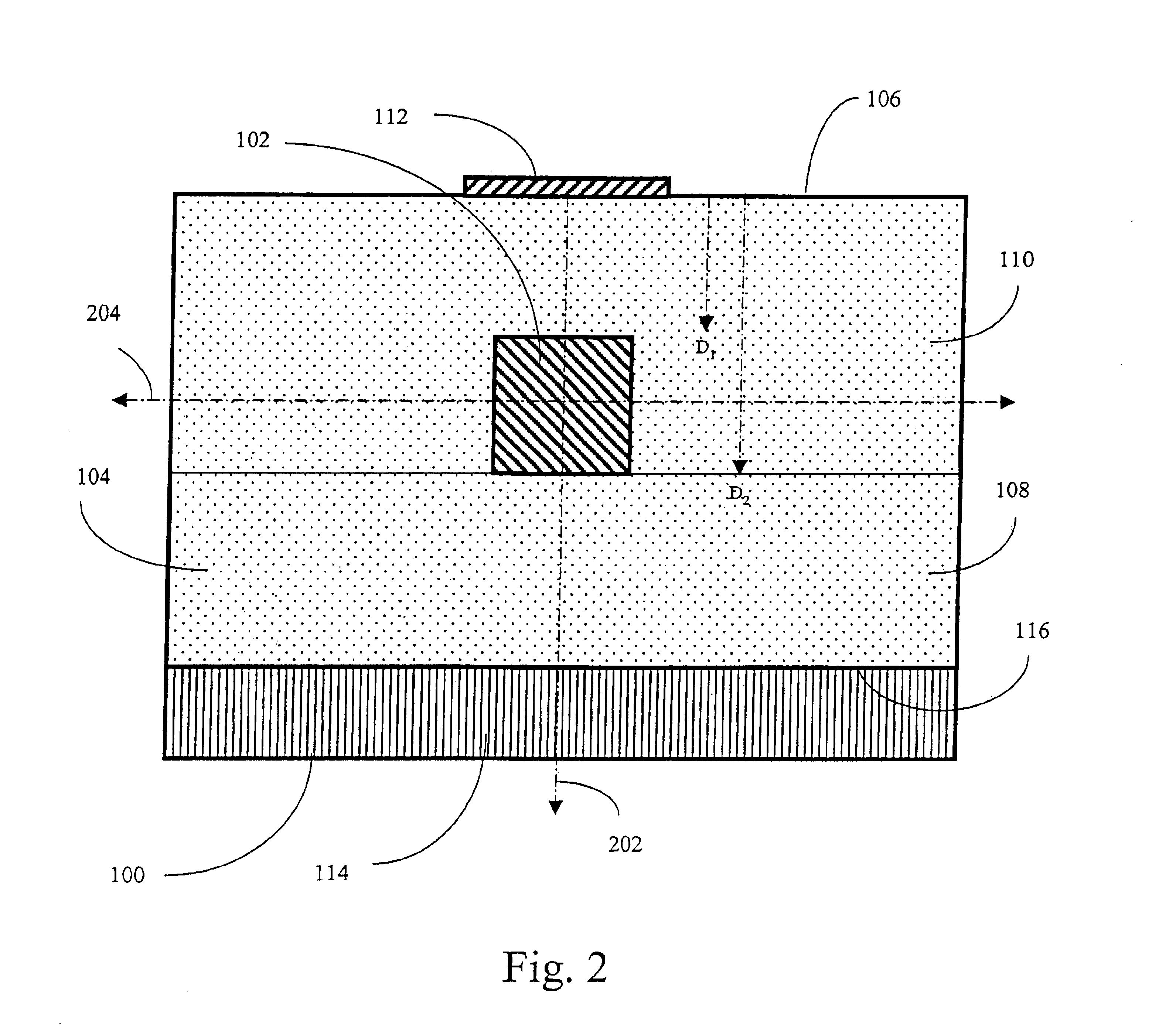
[0025]The present invention generally provides a device and method for variable attenuation of an optical channel wherein optical energy is controllably extracted from a waveguide in a preferred direction by generating a temperature gradient along an axis transverse to the longitudinal axis of the waveguide (it should be noted that the term “optical energy”, as used herein, denotes electromagnetic energy in general without limitation to specific wavelengths or spectral windows). The device is constructed to avoid problems associated with prior art devices, including sensitivity to ambient temperature, thermal cross-talk between adjacent optical channels, and high power consumption. Suitable uses of the device include, without limitation, equalization of optical power levels in input channels of a wavelength division multiplexer device, span balancing, amplifier input balancing, mux-demux balancing, and optical receiver protection.

[0026]FIGS. 1 and 2 depict elements of a variable opt...


PUM


Abstract

A device for variable attenuation of an optical channel includes an elongated core surrounded by a cladding. Optical energy propagating along the longitudinal axis of the core is normally confined thereto by the difference in refractive indices between the core and cladding. The thermo-optic coefficients of the core and cladding are closely matched such that waveguide confinement is substantially invariant with respect to ambient temperature. The device further includes a thermal source arranged above the core. The thermal source is operable to generate a temperature gradient of controllable magnitude along a vertical axis extending through the core. The temperature gradient causes reduction of the local refractive index within the core relative to surrounding regions of the cladding such that a portion of the optical energy is deflected away from the thermal source and extracted from the core.

Description

CROSS-REFERENCE TO RELATED APPLICATION[0002]This application is a continuation of U.S. application Ser. No. 09 / 919,711, filed Aug. 1, 2001, now abandoned which is a continuation-in-part of pending U.S. application Ser. No. 09 / 630,891 entitled “Device and Method for Variable Attenuation of an Optical Channel” by inventors Bischel et al., filed Aug. 2, 2000. The three applications are commonly assigned.BACKGROUND[0003]1. Field of the Invention[0004]The invention relates generally to optical communications, and more specifically to a variable attenuator for removing optical energy from a waveguide in a controllable manner.[0005]2. Description of the Prior Art[0006]The telecommunication industry is making increasing use of optical communication systems for high-bandwidth transmission of voice, video, and data signals. In optical communication systems, it is frequently necessary or desirable to precisely adjust optical signal levels entering various system components. Adjustment of optic...

Claims


Application Information

Patent Timeline
IPC IPC(8): G02F1/01G02F1/065G02B27/28G02F1/31G02F1/29H04J14/02H04J14/06
CPCG02B27/283G02F1/011G02F1/065G02F1/31H04J14/02H04J14/0206H04J14/0208G02F1/0147H04J14/06H04J14/0201H04J14/0209G02F2203/05
Inventor BISCHEL, WILLIAM K.KOWALCZYK, TONY C.
Owner BROADEX TECH UK LTD
Why Eureka
Try Eureka