Method and apparatus for reading invisible symbol

Inactive Publication Date: 2005-02-22
KK TOSHIBA
View PDF7 Cites 29 Cited by
  • Summary
  • Abstract
  • Description
  • Claims
  • Application Information

AI Technical Summary

Benefits of technology

It is an object of the present invention to provide a method and appa

Problems solved by technology

This greatly reduces the working time compared to conventional work in which an operator inputs a price into a register.
A tag or barcode is presently attached to the inside of a linen supply or clothing item where this tag or barcode is difficult to see.
However, this zip code reading is time-consuming and requires manual sorting of mails because read errors sometimes occur.
Although barcodes may be used in mail service, visible barcodes cannot be printed on the surfaces of mails because the barcodes contaminate the mails.
However, a barcode itself cannot unlimitedly shrink, so a fixed exclusive area is necessary.
Unfortunately, the ultraviolet light method has the following problem.
Therefore, it is hi

Method used


Image

  • Method and apparatus for reading invisible symbol
  • Method and apparatus for reading invisible symbol
  • Method and apparatus for reading invisible symbol

Examples


example 1

An acrylonitrile (25%)-styrene (75%) copolymer (AS resin) was used as the material of an invisible barcode. This resin was pulverized to have an average size of 11 μm to prepare toner not containing pigments. This toner was used as toner of a laser beam printer to form an invisible linear barcode on plain paper. The formed barcode corresponds to an enlarged size with a basic width of 3 mm obtained by enlarging a JAN code with a basic width of 300 μm printed on an existing article selected at random.

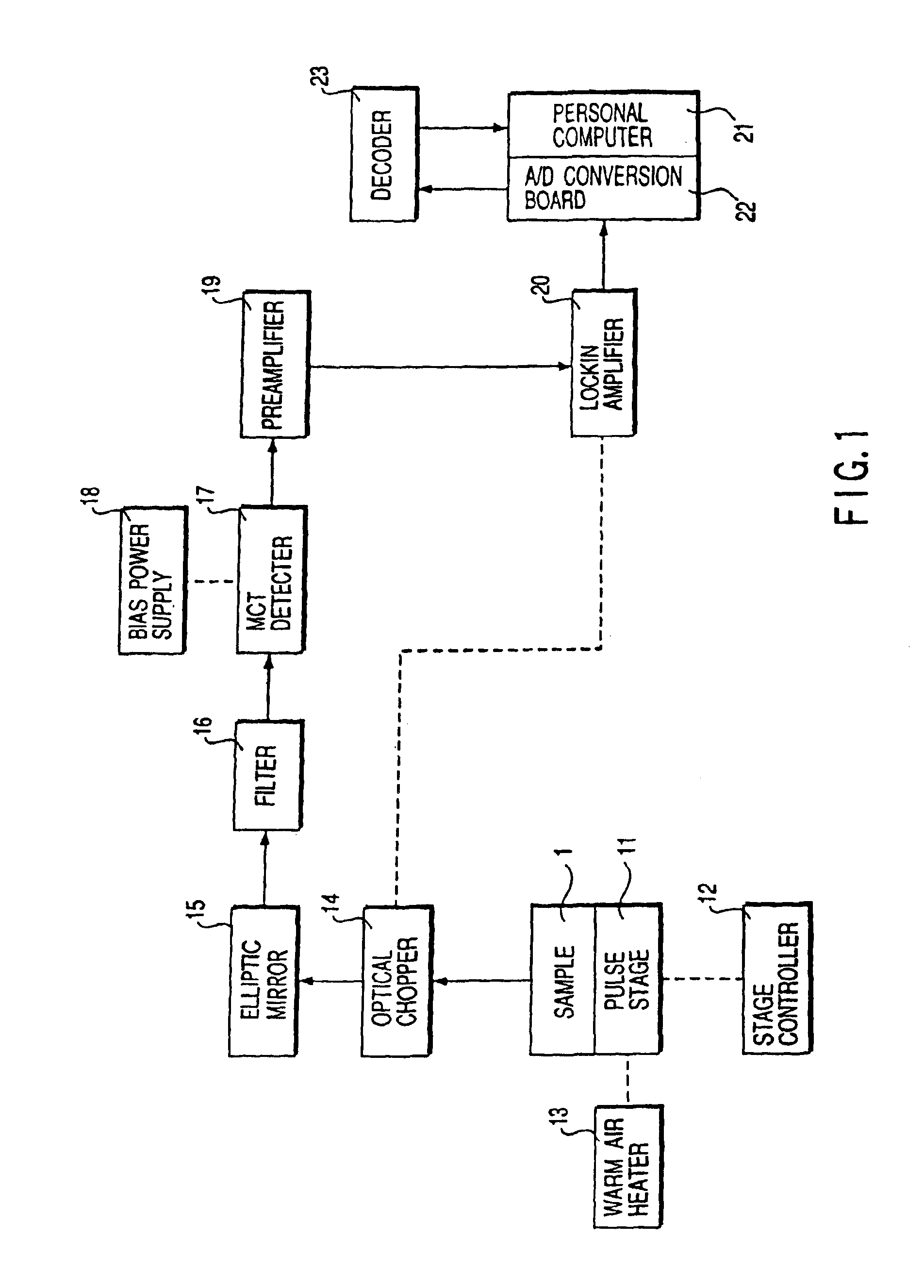
FIG. 1 is a block diagram showing an invisible symbol reading apparatus used in this example. A sample 1 on which the invisible barcode is printed is held on a pulse stage 11. This pulse stage 11 moves in accordance with a signal from a stage controller 12. The sample 1 is heated by warm air blown from a warm air heater 13. This heating excites molecular vibration of a cyano group in the invisible barcode, and infrared emission occurs near 4.5 μm accordingly.

This infrared emission is refl...

example 2

Toner made from the same AS resin as used in Example 1 was used as toner of a laser beam printer to form an invisible barcode on plain paper. The formed barcode corresponds to a standard-size barcode with a basic width of 300 μm printed on an existing article selected at random.

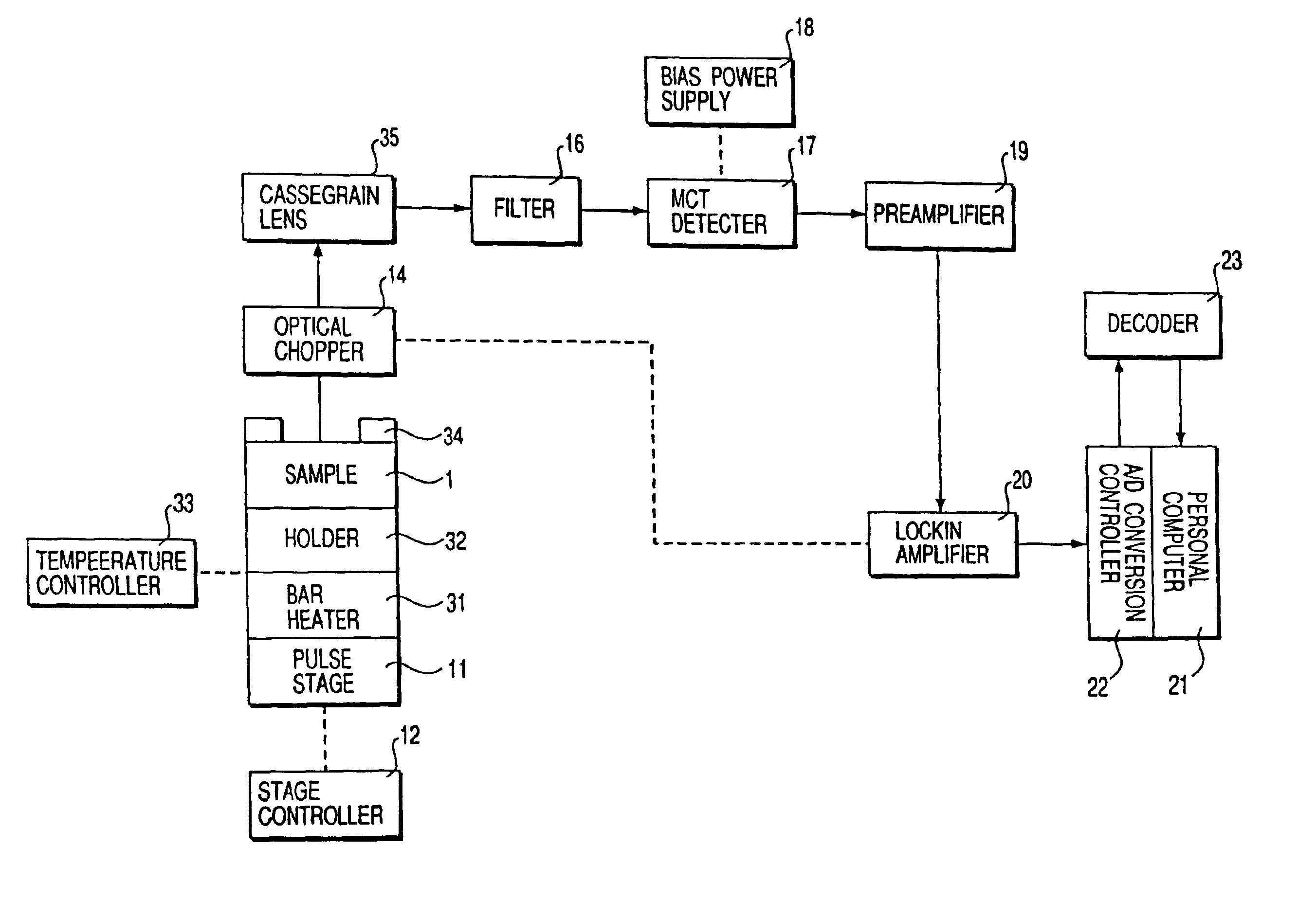
FIG. 6 is a block diagram showing an invisible symbol reading apparatus used in this example. A holder 32 having a built-in bar heater 31 holds a sample 1 on which the invisible barcode is printed on a pulse stage 11. A signal from a built-in thermocouple (not shown) of the holder 32 is input to a temperature controller 33 to adjust the current to be supplied to the bar heater 31, thereby heating the sample 1 to a predetermined temperature. A target 34 is used to align the optical axis of an optical system and a barcode formation region of the sample 1. As shown in FIG. 7A or 7B, this target 34 is a frame-like member, and three or four marks 34a are formed on it. As shown in FIGS. 7A to 7C, the intersection o...

example 3

A polyacrylonitrile powder was dispersed in a 5 wt % aqueous polyvinyl alcohol solution at a ratio of 2 wt % with respect to polyvinyl alcohol. The resultant dispersion was used as ink of an ink jet printer to form an invisible barcode on plain paper. The formed barcode corresponds to the same standard-size barcode with a basic width of 300 μm as in Example 2.

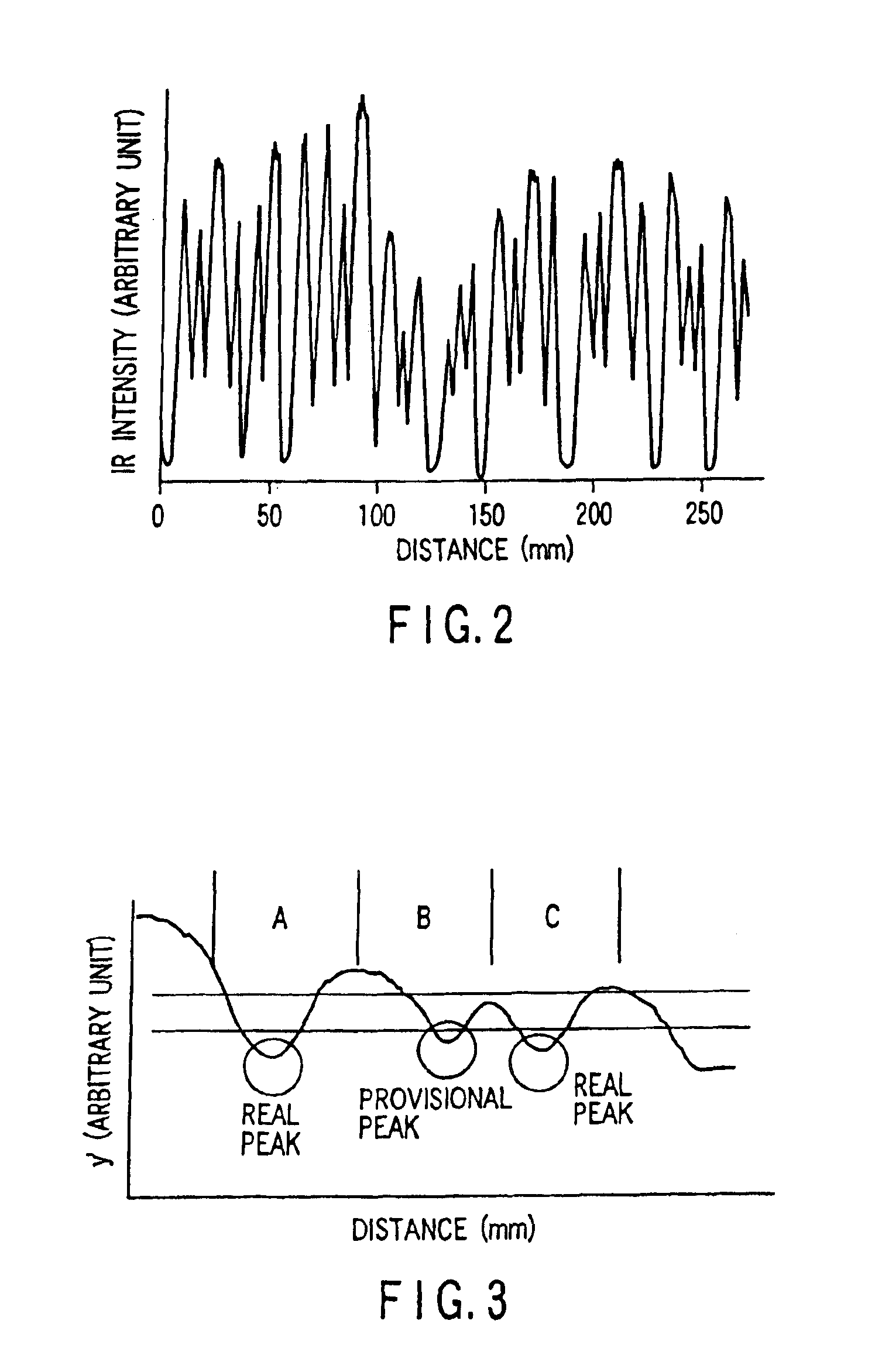
A reading apparatus shown in FIG. 6 was used to heat a sample 1 to 70° C. while a pulse stage 11 was moved at a fixed rate. Infrared emission at a focal point was detected and input to a personal computer 21. The start and end positions of the barcode were measured by taking margins for these positions by using limit switch signals from the pulse stage 11. Following the same procedures as in Example 1, the measured data was smoothed and binarized by differentiation, and the bar and space widths were optimized. This optimized data was decoded by a decoder 23, the decoded data matched the result of decoding of the original data.


PUM


Abstract

An article including a substrate and an invisible symbol on the substrate is disclosed. The invisible symbol is formed by a compound which includes a cyano group and has an infrared absorption wavelength apart from that of the substrate when heated.

Description

BACKGROUND OF THE INVENTIONThe present invention relates to a method and apparatus for reading invisible symbols (linear barcodes and two-dimensional symbols) usable in mail service, distribution of articles whose appearances are important, management of documents and articles requiring secrecy, and prevention of forgery.Barcodes or two-dimensional symbols representing information about a manufacturing country, manufacturer, and product items are printed or pasted as labels on many articles currently distributed on the market. When an operator uses an optical reader to read a barcode, a corresponding price is read out from a database. This greatly reduces the working time compared to conventional work in which an operator inputs a price into a register. Stock control is also made efficient by constructing a POS system. Additionally, barcodes are effective to increase the efficiency of express delivery.On the other hand, barcodes cannot be attached to some articles, and it is better ...

Claims


Application Information

Patent Timeline
IPC IPC(8): G06K7/14
CPCG06K7/14
Inventor URANO, TAEKO I.SANO, KENJINAGAI, HIDEODOMON, TOMOKAZUFUKUDA, HIRONORI
Owner KK TOSHIBA
Why Eureka
Try Eureka