Polluted water treatment system

a water treatment system and polluted water technology, applied in the direction of water cleaning, water treatment parameter control, feed/outtake of settling tanks, etc., can solve the problems of low filter effect, non-uniform loading of filters, and low efficiency in nitrogen removal, so as to reduce impurities of polluted water and control the level of inflow polluted water

Inactive Publication Date: 2005-02-22
ROOTZONE AUSTRALIA
View PDF26 Cites 24 Cited by
  • Summary
  • Abstract
  • Description
  • Claims
  • Application Information

AI Technical Summary

Benefits of technology

According to a second broad aspect of the invention, there is provided a constructed wetland polluted water treatment method for substantially reducing impurities of polluted water, the method comprising the steps of:(a) permitting polluted water to flow into an inlet zone of a primary filter bed(b) removing at least a portion of said impurities in a treatment zone;(c) removing treated polluted water from an outlet zone adjacent to an end of said treatment zone;(d) treating water from the outlet zone of the primary filter bed in a secondary filter and recycling a portion of the water leaving the secondary filter to the primary filter bed and disposing of the remainder of the water from the secondary filter bed; and(e) controlling the level of inflow polluted water in said inlet zone by regulating the quantity of treated polluted water recycled in step (d).

Problems solved by technology

Both HSFs and VFs are very efficient at breaking down organic pollutants (BOD and COD) and retaining suspended solids from waste water but they are much less efficient at removing nitrogen and in the case of phosphorus or heavy metals the effect is very low without very substantial increases being made in the size of the filter.
Another potential disadvantage of these filters is that the loading of the filter may (and frequently does) occur in a non-uniform manner due to the requirements of the facility which the filter is servicing.
This can result in inefficient use of the filter and results in a larger filter being required to service particular facilities.
This can subsequently increase the costs of constructing the filter.

Method used


Image

  • Polluted water treatment system
  • Polluted water treatment system
  • Polluted water treatment system

Examples


Embodiment Construction

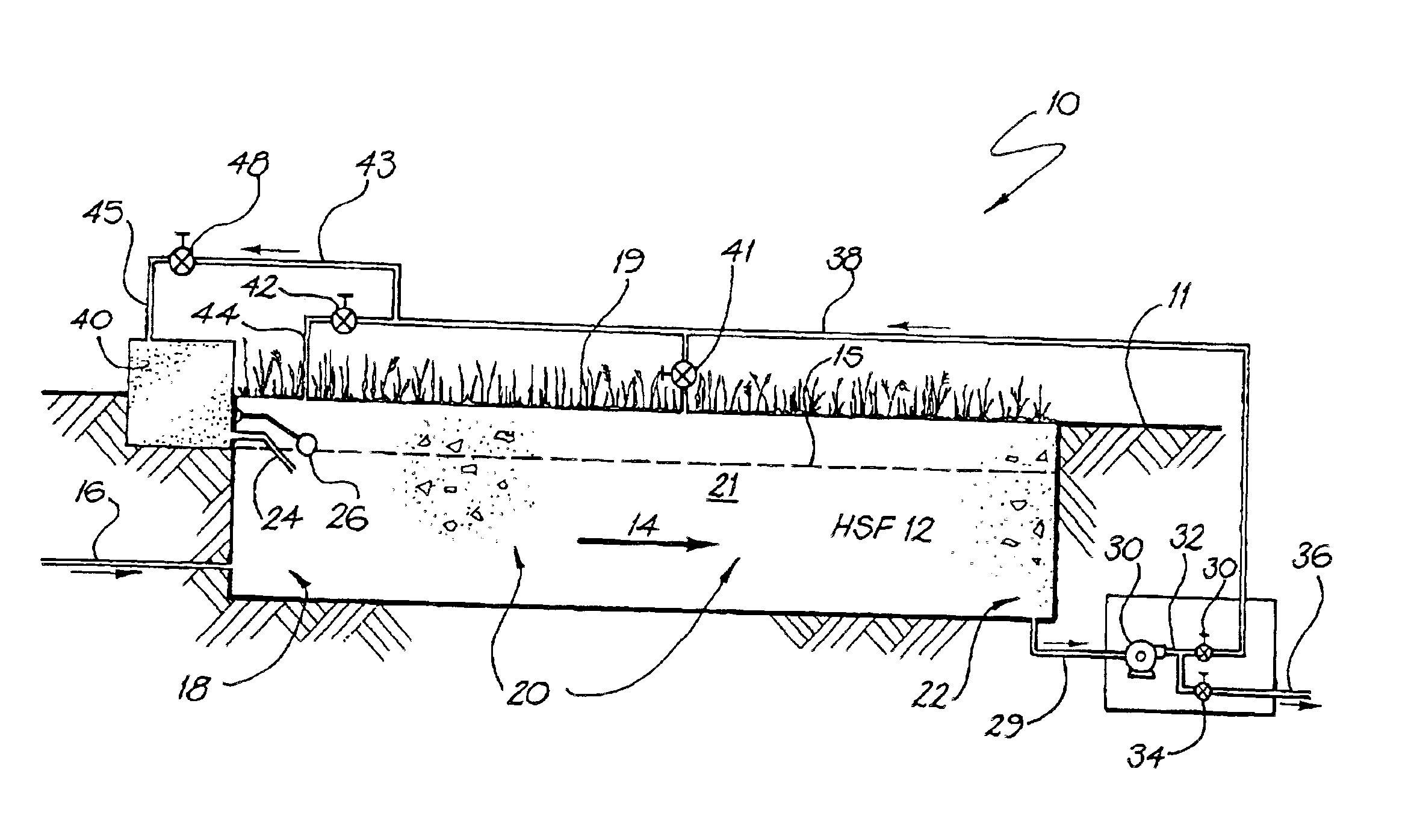
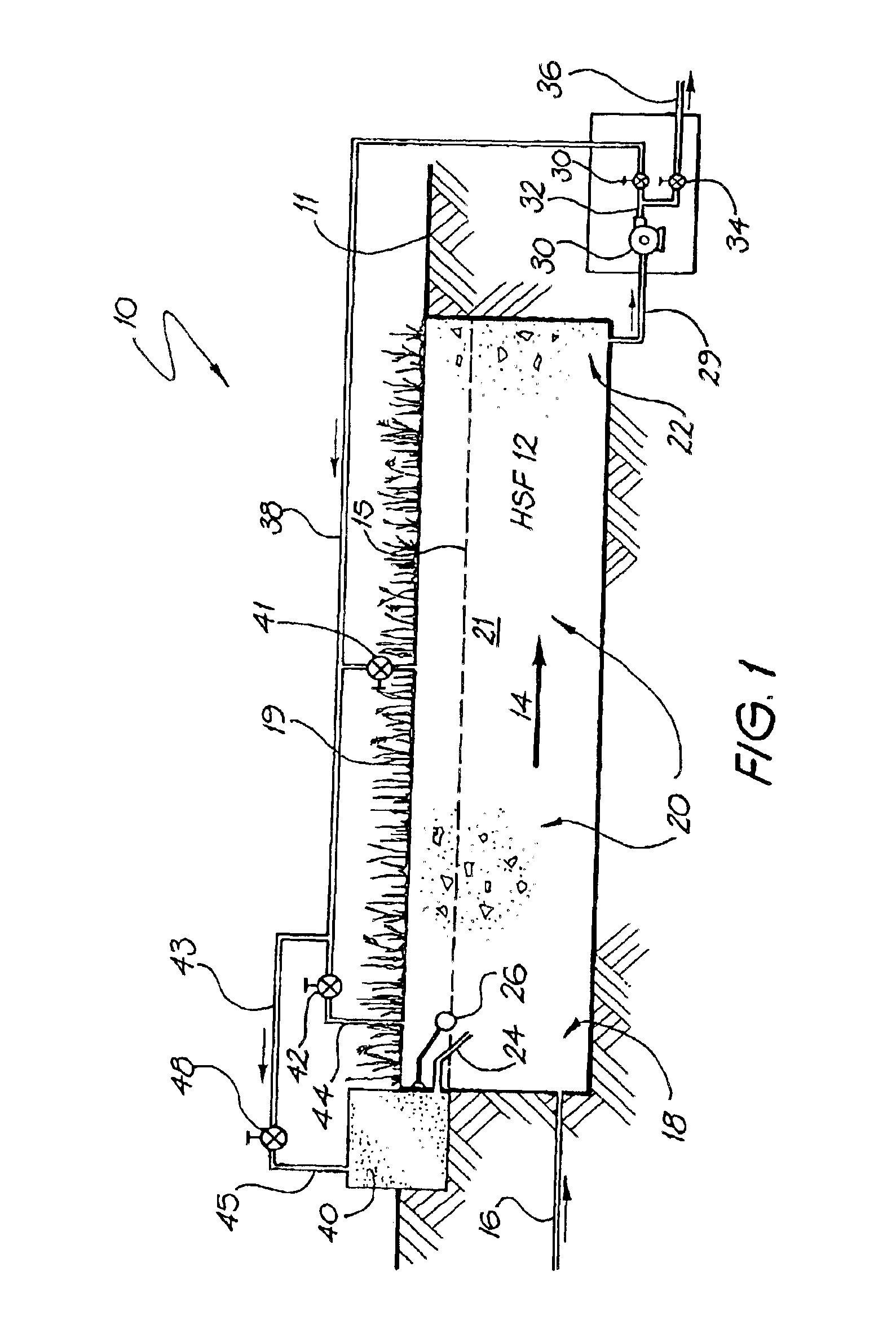
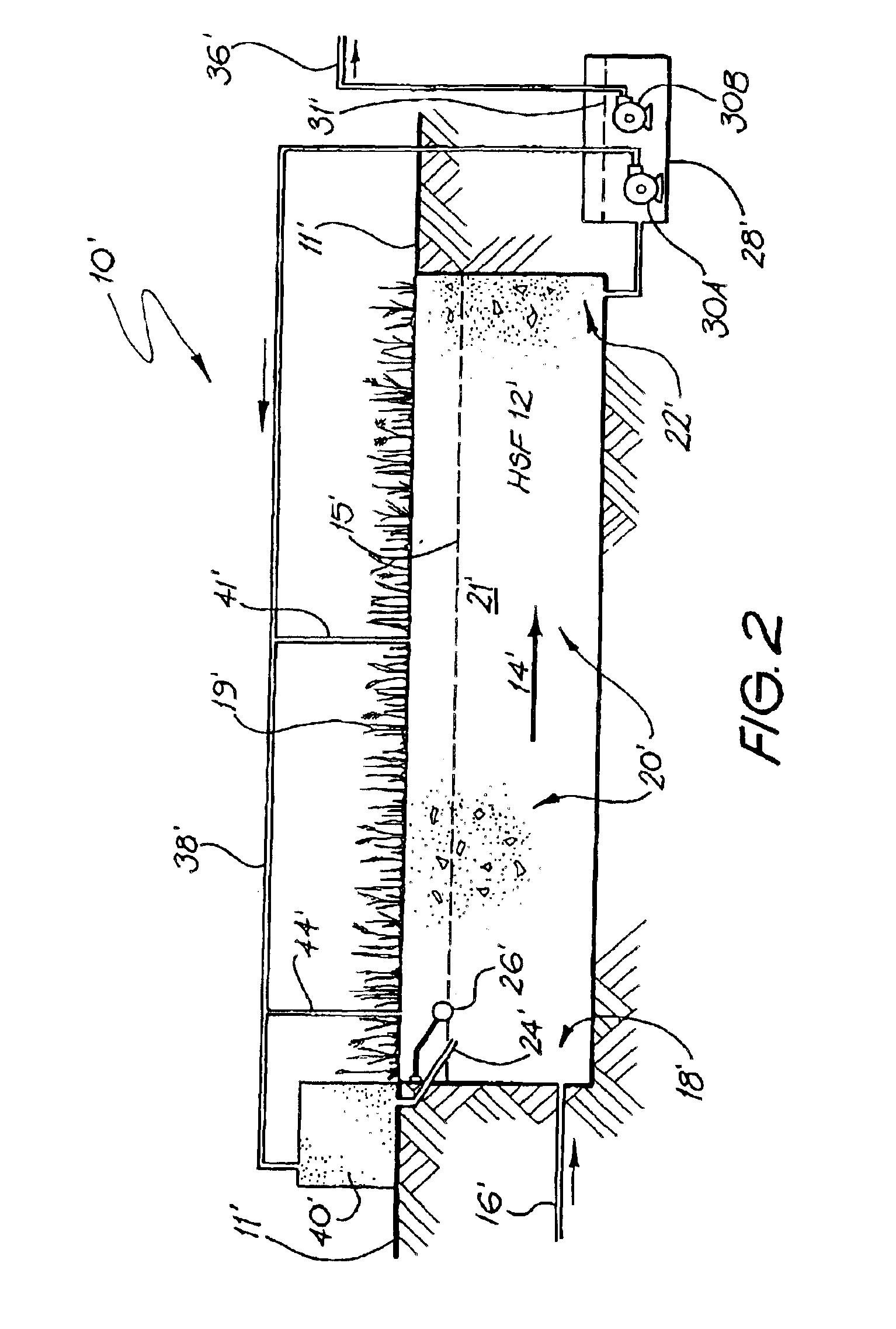
A preferred embodiment of a sewage waste water treatment system will now described with reference to FIGS. 1 and 2. This embodiment is not claimed. A waste water treatment system is operated to reduce impurities in sewerage waste water to an acceptable level for dumping. The system includes a horizontal subsurface filter (HSF) bed having an inlet zone through which the inflow of waste water is permitted to pass, a treatment zone which permits the waste water to undergo treatment by removal of at least some of the impurities of the polluted water and an outlet zone from which the treated waste water flows from the HSF bed and a collection well from which the treated waste water can be redirected.

The impurities may include, for example, organic materials (BOD and COD) and nutrients such as nitrogen and phosphorus. The collection well has a pump located therein to recycle the treated effluent back to either the inlet zone or the treatment zone of the HSF or to a secondary vertical filt...


PUM

PropertyMeasurementUnit
depthsaaaaaaaaaa
flow rateaaaaaaaaaa
flow rateaaaaaaaaaa

Abstract

A polluted water treatment system 10 operated to reduce impurities in sewerage polluted water to an acceptable level for dumping. The system includes a horizontal subsurface filter (HSF) 12 having an inlet zone 18 through which the inflow of polluted water is permitted to pass, a treatment zone 20 which permits the polluted water to undergo treatment by removal of at least some of the impurities of the polluted water and an outlet zone 22 from which the treated polluted water flows from the HSF 12. The impurities may include, for example, organic materials (BOD and COD) and oxidization processes within the HSF may reduce the quantity of the nitrites that are dumped from the outflow zone 22. The outlet zone 22 also includes a collection well 28 having a pump 30 located therein to recycle the treated effluent back to either the inlet zone 18 of the HSF 12 or to a secondary vertical filter 40. A level switch 26 located in the inlet zone 18 of the HSF 12 controls the level of water in the inlet zone to a set level 15 by regulating the amount of recycle water returned to the HSF 12 or indirectly via the vertical filter 40. The vertical filter 40 may be used to pre-treat any polluted water before it enters the HSF 12 and furthermore, it may also be used to remove phosphates from the polluted water.

Description

FIELD OF THE INVENTIONThe present invention relates to a polluted water treatment system and to a method of control and installation of same.BACKGROUND OF THE INVENTIONFilters are often used to remove impurities from polluted water systems. One known set of filters is based on the fact that polluted water can be passed through a media which is planted with emergent macrophytes and under the action of bacterial and chemical reactions and adsorption by the media pollutants are broken down or adsorbed by the filter. Such filters are commonly known by the generic name of constructed wetlands. Flow may be either vertical or horizontal. In the art, if the flow within a filter is horizontal, it is known colloquially as a “Horizontal Subsurface Filter” (HSF) and if vertical, it is known colloquially as a “Vertical Filter” (VF).Both HSFs and VFs are very efficient at breaking down organic pollutants (BOD and COD) and retaining suspended solids from waste water but they are much less efficien...

Claims


Application Information

Patent Timeline
Patent Type & Authority Patents(United States)
IPC IPC(8): C02F3/00C02F3/30C02F3/32
CPCC02F3/006C02F3/327C02F3/302C02F1/001Y10S210/906C02F2209/42Y02W10/10
Inventor TOWNDROW, ANTHONY PHILIP
Owner ROOTZONE AUSTRALIA
Why Eureka
Try Eureka