Circuit and method for energy discrimination of coincident events in coincidence detecting gamma camera system

US6858847B1Inactive Publication Date: 2005-02-22SIEMENS MEDICAL SOLUTIONS USA INC

Image

  • Circuit and method for energy discrimination of coincident events in coincidence detecting gamma camera system
  • Circuit and method for energy discrimination of coincident events in coincidence detecting gamma camera system
  • Circuit and method for energy discrimination of coincident events in coincidence detecting gamma camera system

Examples


first embodiment

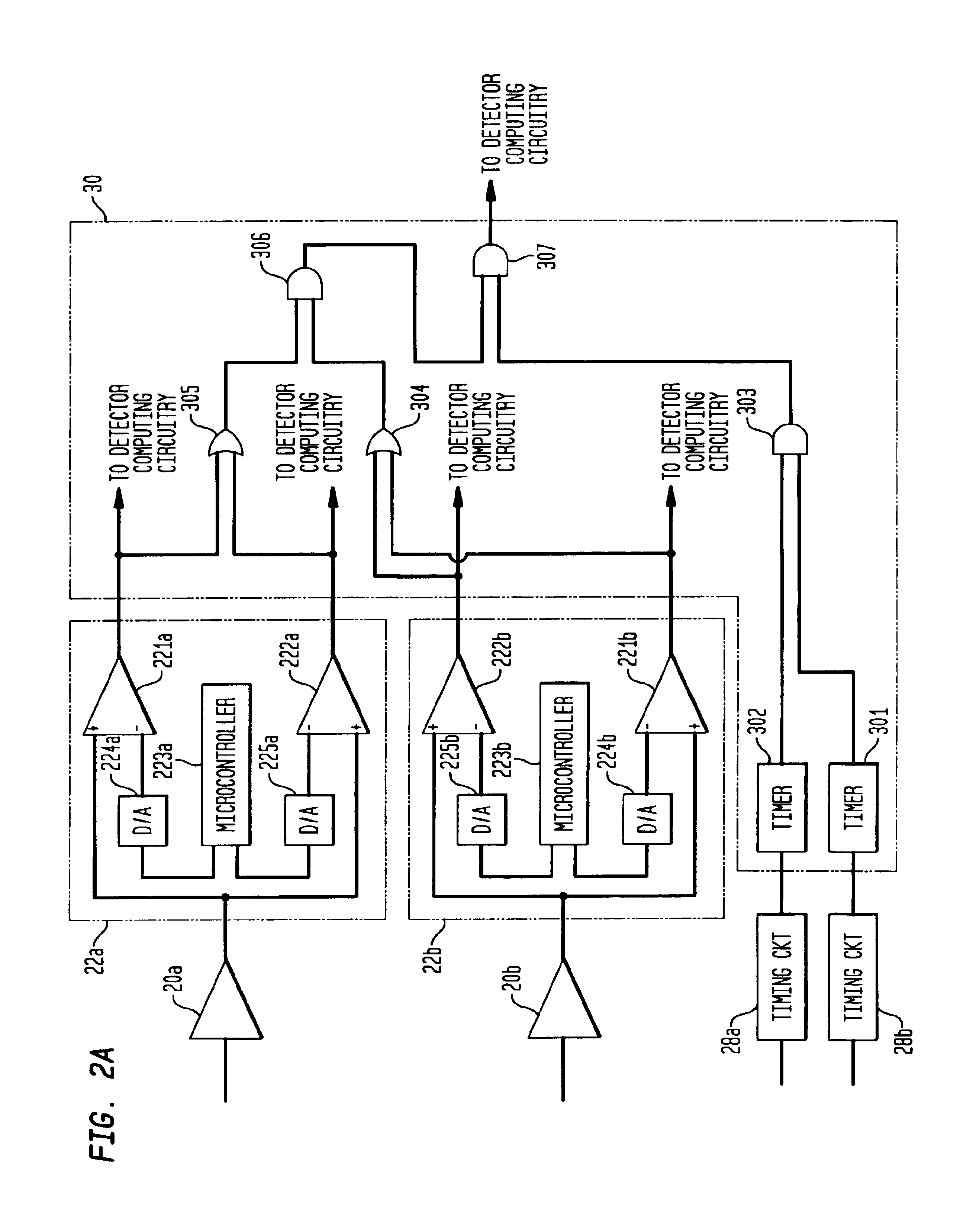
FIG. 2A is a schematic diagram showing details of the energy comparator circuits 22a, 22b and logic circuits 30 according to the invention. Each energy comparator includes a dual comparator 221, 222. The inverting input of comparator 221 is provided with the photopeak energy level outputted by microcontroller 223 through a digital-to-analog (D / a) converter 224. The inverting input of comparator 222 is provided with the Compton scatter energy level produced by the microcontroller and applied to D / a converter 225. The output event signal is applied to the noninverting inputs of each comparator 221, 222. The outputs of comparators 221a and 222a are inputted to OR gate 305, and the outputs of comparators 221b and 222b are inputted to OR gate 304. The outputs of OR gates 304 and 305 are inputted to AND gate 306. The outputs of the comparators may be also sent to the detector computing circuitry for use in position calculation. As such, a signal will be outputted by AND gate 306 if the en...

second embodiment

the energy comparator circuits and logic circuits is shown in FIG. 2B. In this embodiment, a third OR gate 308 is supplied with the outputs from the photopeak level comparators 221a, 221b of each detector. The output of OR gate 308 is inputted to a three-input AND gate 306a, along with the outputs from OR gates 304 and 305. Thus, an output signal from AND gate 306a will be produced only if at least one of the events in each detector is a photopeak event. This embodiment prevents a positron event from being counted in the acquired image if both photons are Compton scatter photons. In such case, there exists a significant probability that the photons were scattered within the patient's body, and thus the computation of the point of origin of the positron event would be less reliable than desired.

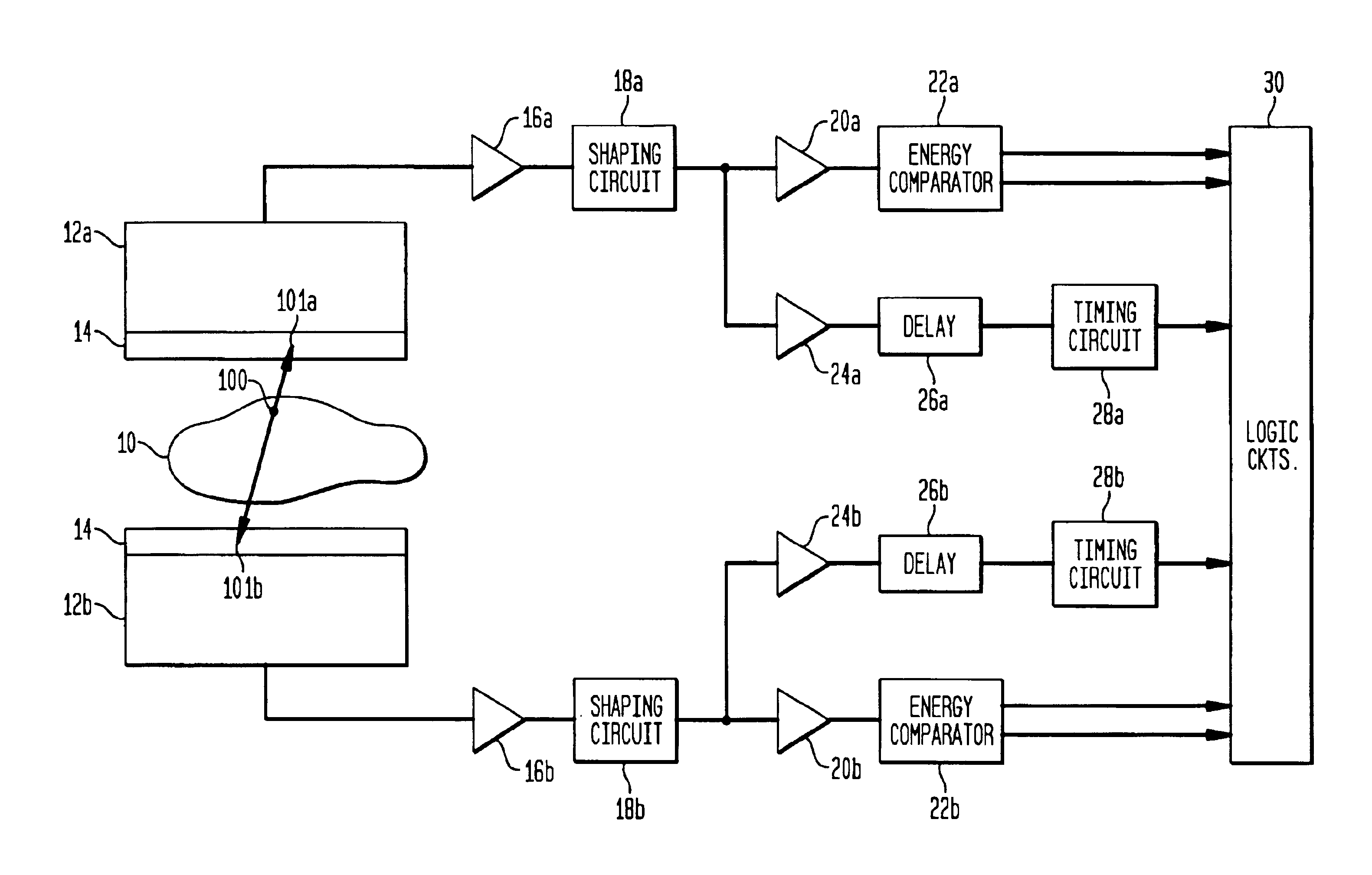
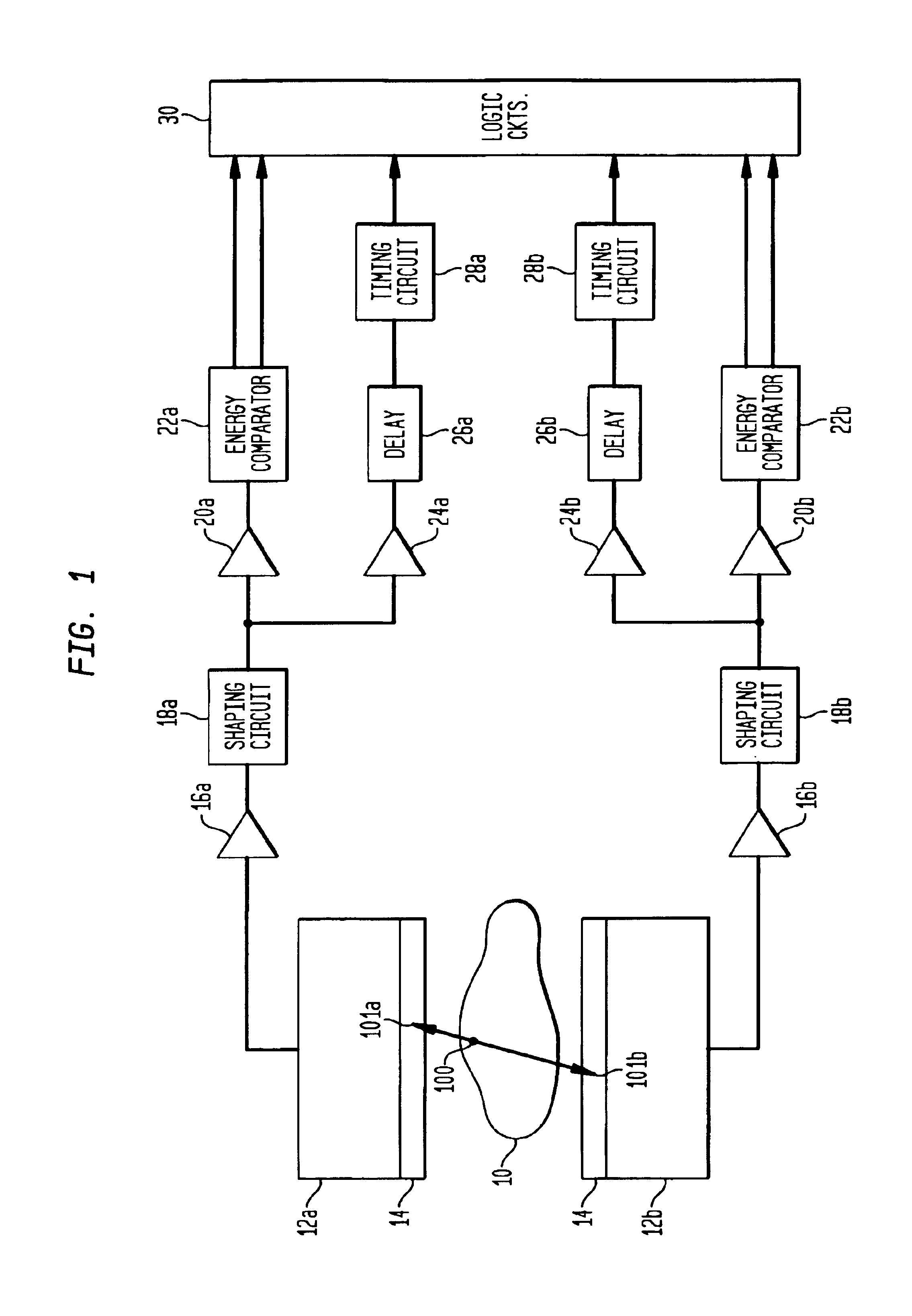
Timing circuits 28a and 28b provide start signals to timers 301, 302 in response to receipt of event signals. In response to the start signals, each timer produces an output signal for a prede...


PUM


Abstract

A positron imaging system includes a pair of scintillation detectors for detecting a pair of gamma rays produced by annihilation of a positron within a distribution field, such as within a patient. An energy level determination circuit determines the energy levels of the detected gamma rays, and timing circuits determine whether the gamma rays have been detected by the scintillation detectors within a predetermined time interval. Only if the determined energy levels of each of the pair of gamma rays meet predetermined magnitude requirements and detection of the pair of gamma rays has occurred within the predetermined time interval, are signals corresponding to said gamma rays inputted to processing circuitry for calculating the spatial location of the positron. According to a further aspect of the invention, a circuit for separating piled-up gamma ray events includes a delay and a controllable attenuator for delaying and simultaneously attenuating a signal outputted by the detector, and a comparator for comparing the delayed signal with the attenuated signal, to thereby output separate electrical pulses representing the separate events.

Description

BACKGROUND OF THE INVENTION1. Field of the InventionThe present invention generally relates to nuclear medicine, and systems for obtaining nuclear medicine images of a patient's body organs of interest. In particular, the present invention relates to systems and methods for obtaining nuclear medicine images by detecting coincident events resulting from positron annihilation.2. Description of the Background ArtNuclear medicine is a unique medical specialty wherein radiation is used to acquire images which show the function and anatomy of organs, bones or tissues of the body. Radiopharmaceuticals are introduced into the body, either by injection or ingestion, and are attracted to specific organs, bones or tissues of interest. Such radiopharmaceuticals produce gamma photon emissions which emanate from the body and are captured by a scintillation crystal, with which the photons interact to produce flashes of light or โ€œevents.โ€ Events are detected by an array of photodetectors, such as p...

Claims


Application Information

Patent Timeline
22 Feb 2005
Publication
US6858847B1
IPC
G01T1/164; G01T1/00; G01T1/29
CPC
G01T1/2985; A61B6/037
Inventors
MACCIOCCHI, FRED