Photon operating device and photon operating method
- Summary
- Abstract
- Description
- Claims
- Application Information
AI Technical Summary
Benefits of technology
Problems solved by technology
Method used
Image
Examples
first embodiment
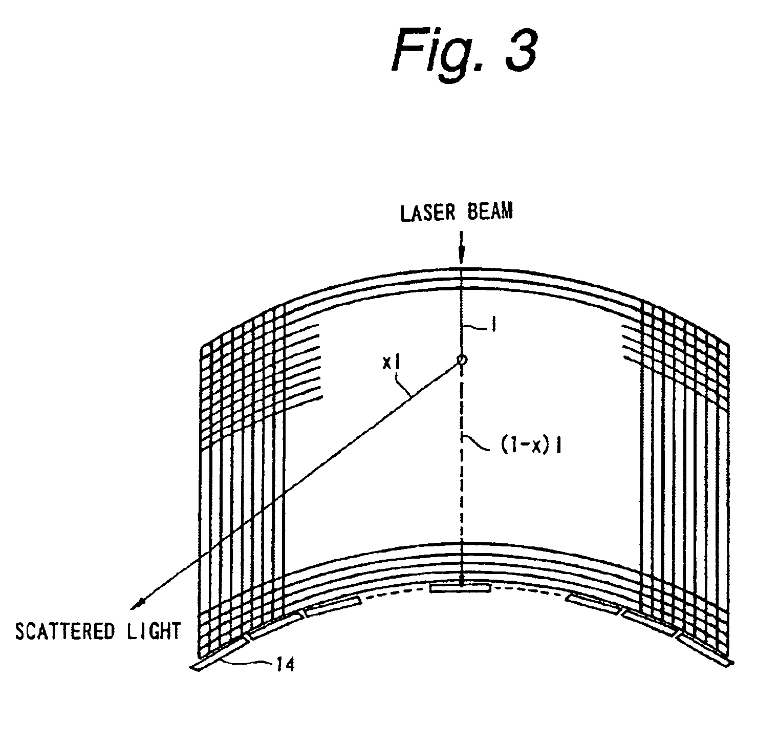
FIG. 3 shows entire configuration of a flat color display having a tactual representation function according to the invention. FIG. 4 shows a part of the flat color display having the tactual representation function in an enlarged scale.
As shown in FIGS. 3 and 4, the flat color display is made up of a plurality of straight optical fibers 1 for image display aligned in parallel, and a plurality of straight optical fibers 12 aligned in parallel to each other to intersect with the optical fibers 11, thereby to form a rectangular sheet, and the entirety is curved in the lengthwise direction of the control signal lines 3 and 4 to form a concave display plane. Intersection points of these optical fibers 11 and optical fibers 12 form optical switches.
The number of optical fibers 11 depends on the number of pixels aligned in the lengthwise direction of the optical fibers 12. More specifically, three optical fibers 11 are provided per pixel for R (red), G (green) and B (blue), respectively, ...
second embodiment
Next explained is a flat color display according to the invention.
As shown in FIG. 9, the second embodiment uses optical fibers 21 and optical waveguides 22 instead of optical fibers 11, 12 of the first embodiment. In the other respects, the second embodiment is the same as the first embodiment.
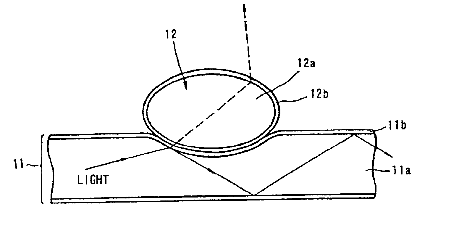
As shown in FIG. 9, linear optical waveguides 22 are provided to intersect and contact with optical fibers 21 made up of cores 21a and claddings 21b. In selective portions of claddings 21b at intersections with the optical fibers 21 and the optical waveguides 22, Au fine particles are dispersed.
In the flat color display, light is introduced from one end of each optical fiber 21. More specifically, blue light or red light is introduced. Under the condition, when green light with the wavelength of 530 nm (2.3 eV in photon energy) is introduced as control light into an optical waveguide 22, evanescent light is generated in the cladding 21b of a portion of the optical fiber 21 in contact with the...
third embodiment
Next explained is a flat color display according to the
As shown in FIG. 13, the third embodiment uses optical fibers 31 and optical waveguides 32 instead of optical fibers 11, 12 of the first embodiment. In the other respects, the third embodiment is the same as the first embodiment.
As shown in FIG. 13, each optical fiber 31 is made by making a two-dimensional array of a plurality of elongated rod-shaped photonic crystal 33 bound together, and arranging a plurality of such two-dimensional arrays around a core 34 to form a cladding. Each optical waveguide 32 is provided to intersect and contact with the optical fibers 31.
In the flat color display, light is introduced from one end of each optical fiber 31. Under the condition, when light is introduced as control light into an optical waveguide 32, the light penetrates into the photonic crystals 33 forming the cladding of the optical fiber 31 at the contact with the optical waveguide 32 and changes the photonic band gap such that total...
PUM
 Abstract
Description
Claims
Application Information
 - R&D
- Intellectual Property
- Life Sciences
- Materials
- Tech Scout
- Unparalleled Data Quality
- Higher Quality Content
- 60% Fewer Hallucinations
Browse by: Latest US Patents, China's latest patents, Technical Efficacy Thesaurus, Application Domain, Technology Topic, Popular Technical Reports.
© 2025 PatSnap. All rights reserved.Legal|Privacy policy|Modern Slavery Act Transparency Statement|Sitemap|About US| Contact US: help@patsnap.com


