

Method of manufacturing a thermally conductive circuit board with a ground pattern connected to a heat sink
- Summary
- Abstract
- Description
- Claims
- Application Information
AI Technical Summary
Benefits of technology
Problems solved by technology
Method used
Image

Examples
first embodiment
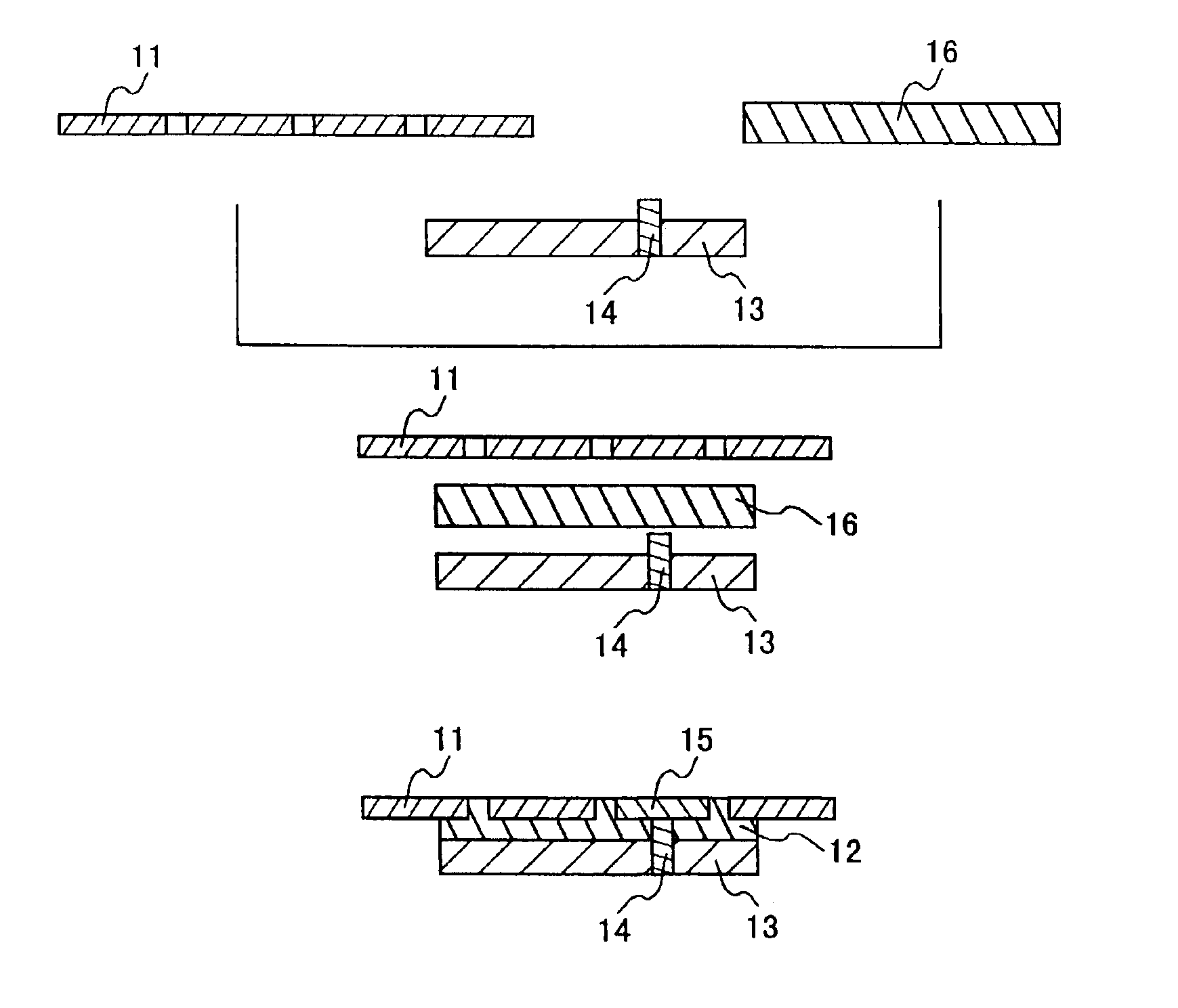
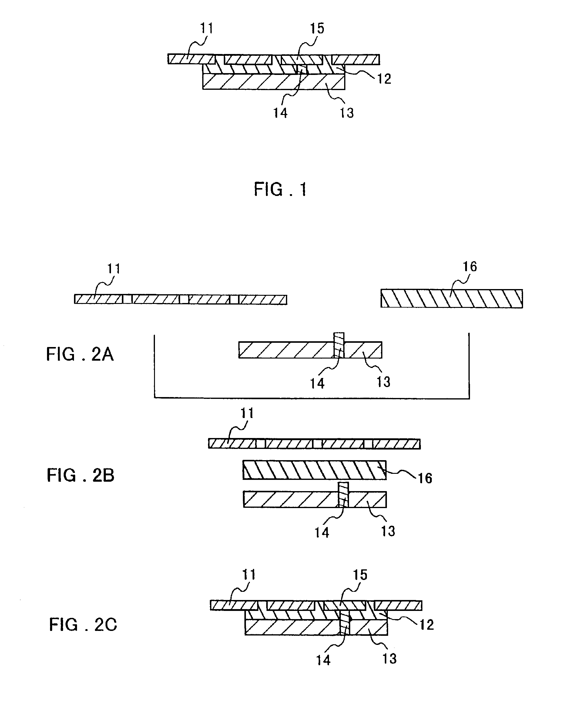
In the present invention, during the formation of the thermally conductive board described above, a protrusion such as a metal pole or the like is provided in an arbitrary place in the wiring pattern or the heat sink in advance, the protrusion is placed and superposed to face the thermally conductive resin composition, and the whole is heated and compressed, so that a ground connection is established between the heat sink and a part of the wiring pattern during the formation of the board.
second embodiment
In the present invention, during the formation of the thermally conductive board described above, a protrusion such as a metal pole or the like is provided in an arbitrary place in the heat sink in advance, the protrusion is placed and superposed to face the thermally conductive resin composition, and the whole is heated and compressed, so that the protrusion is formed as a grounding pattern at the same time the board is formed.
third embodiment
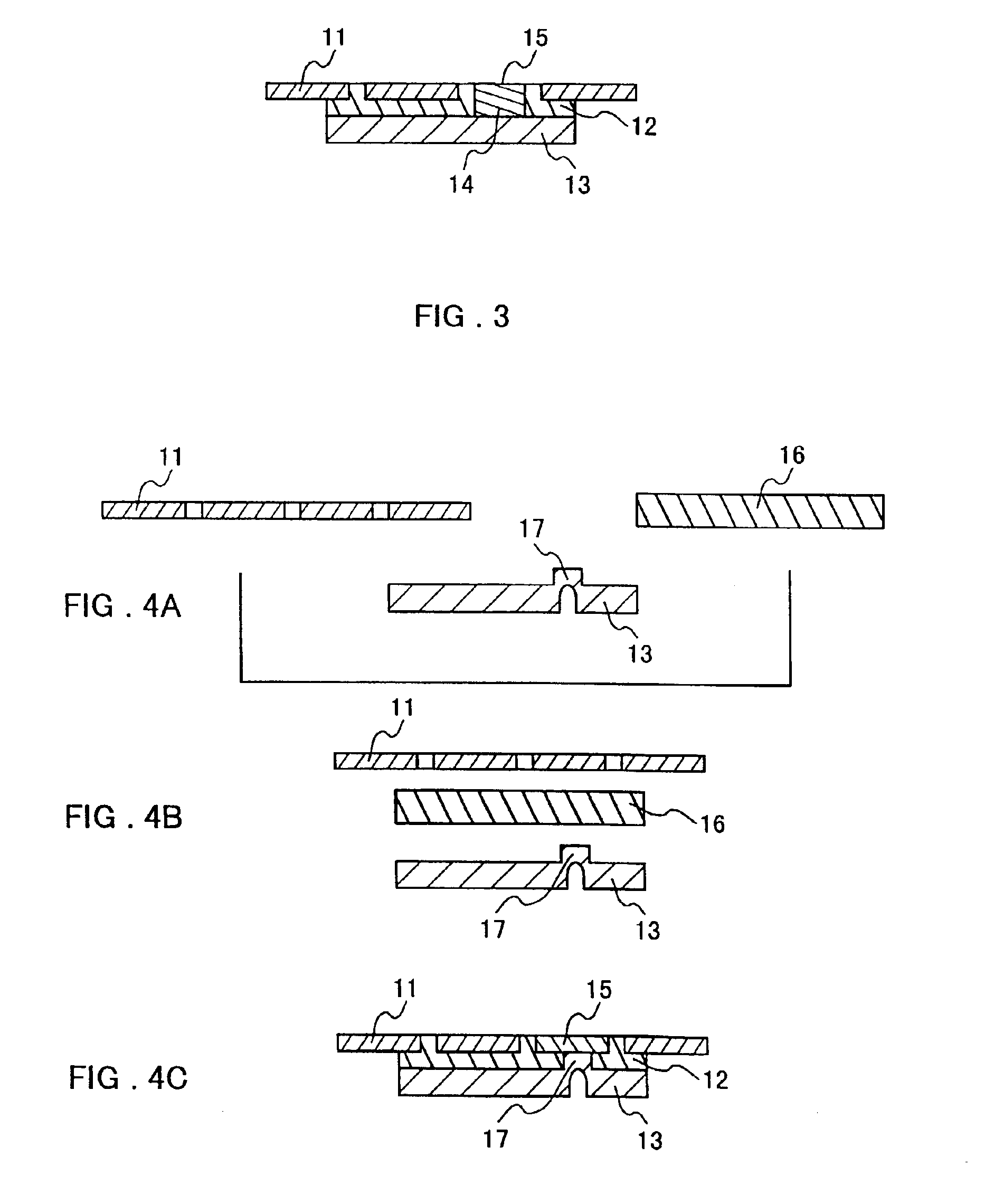
In the present invention, during the formation of the thermally conductive board described above, a metal pole or an electrically conductive resin composition is inserted into an arbitrary place in a thermally conductive resin composition preformed in a sheet shape so as to go through the sheet-like thermally conductive resin composition, this is superposed with a lead frame as a wiring pattern and a heat sink, they are heated and compressed to be combined to form one body, and a ground connection is established between a part of the wiring pattern and the heat sink.
PUM
| Property | Measurement | Unit |
|---|---|---|
| Electrical conductivity | aaaaa | aaaaa |
| Density | aaaaa | aaaaa |
| Electrical conductor | aaaaa | aaaaa |
Abstract
Description
Claims
Application Information