Fiber stuffing and fluffing machine

Inactive Publication Date: 2005-03-01
COLLIDA KARL
View PDF6 Cites 10 Cited by
  • Summary
  • Abstract
  • Description
  • Claims
  • Application Information

AI Technical Summary

Benefits of technology

The present invention overcomes the aforementioned prior art problems by first incorporating one or more unique diverting blast gate valves at its output which allows switching among multiple stuffing machines connected to a single fluffer. That is, when a stuffing machine requires filling by the fluffer, a blast gate valve may be openly positioned to direct the flow to the desired stuffing machine and thereafter fill the agitation cavity with the desired amount of stuffing fiber. In a preferred embodiment, the blast gate valve is pneumatically opened and closed. Alternative embodiments may utilize manual, hydraulic, or electrical control. Furthermore, the prior art noise problem is alleviated by placing sound absorbing foam material within the fluffer housing, especially near the blower and blower motor.
The present invention also overcomes the aforementioned prior art problems by providing an embodiment having an integrated stuffer and fluffer combination. That is, an embodiment of the present art places the stuffer and fluffer into a single stand alone machine also having an integrated air supply and operating from a single power source. Due to the technical difficulties of integrating all of the aforementioned components, the prior art has yet to provide said integration. The stand alone unit of the present art allows for sound isolation, ease of setup, ease of use, and foreign object separation, all within one package. An alternate embodiment of the integrated stuffer-fluffer may utilize the blast gate valve to feed stuffing material to a separate and stand alone stuffing machine, thereby eliminating the need for another stand alone fluffer. Furthermore, the duct or pipe between the fluffer and stuffer may be diverted external to the machine and manufactured of a clear material, whether integrated or stand alone, to allow visualization of the fiber flow between the fluffing and stuffing machines.
The unique blast gate valve design of the present art incorporates novel features which minimize buildup and clogging within said valve. Blast gate valves typically have circular entrance and exiting ports into which feeding and exiting pipes are placed and further have a reduced diameter circular mid-section between said pipes which is substantially the same diameter as the interior diameter of said pipes. Typically the pipes are of a PVC material. Prior art blast gate valve designs utilize a manually operated blade which seats into a groove or slot when closed. The present art utilizes a pneumatically operated blade, with a unique pneumatic cylinder and alignment coupler system, which does not mate into a groove or slot. That is, the prior art blast gate valve seating grooves or slots allow stuffing fibers to build up into said slots when the blast gate closes. Continued use of the prior art valve design creates more fiber buildup which prohibits the valve from completely closing. Within the present art, the blast gate blade is perfectly shaped to seat against a half circular seat which follows the contours of the blast gate mid-section. The seat is flush in a substantially half circle radius with the circular outline of the circular mid-section whereby fibers cannot be trapped. The aforementioned foreign object ingestion problem is eliminated in an embodiment of the present art via the use of a feed separation plenum at the entrance to the fluffer. The

Problems solved by technology

The turbine compressor provides the desired high volume airflow in a compact package with a limited noise output, yet has a limited pressure output which requires the feed orifices within the a

Method used


Image

  • Fiber stuffing and fluffing machine
  • Fiber stuffing and fluffing machine
  • Fiber stuffing and fluffing machine

Examples


Embodiment Construction

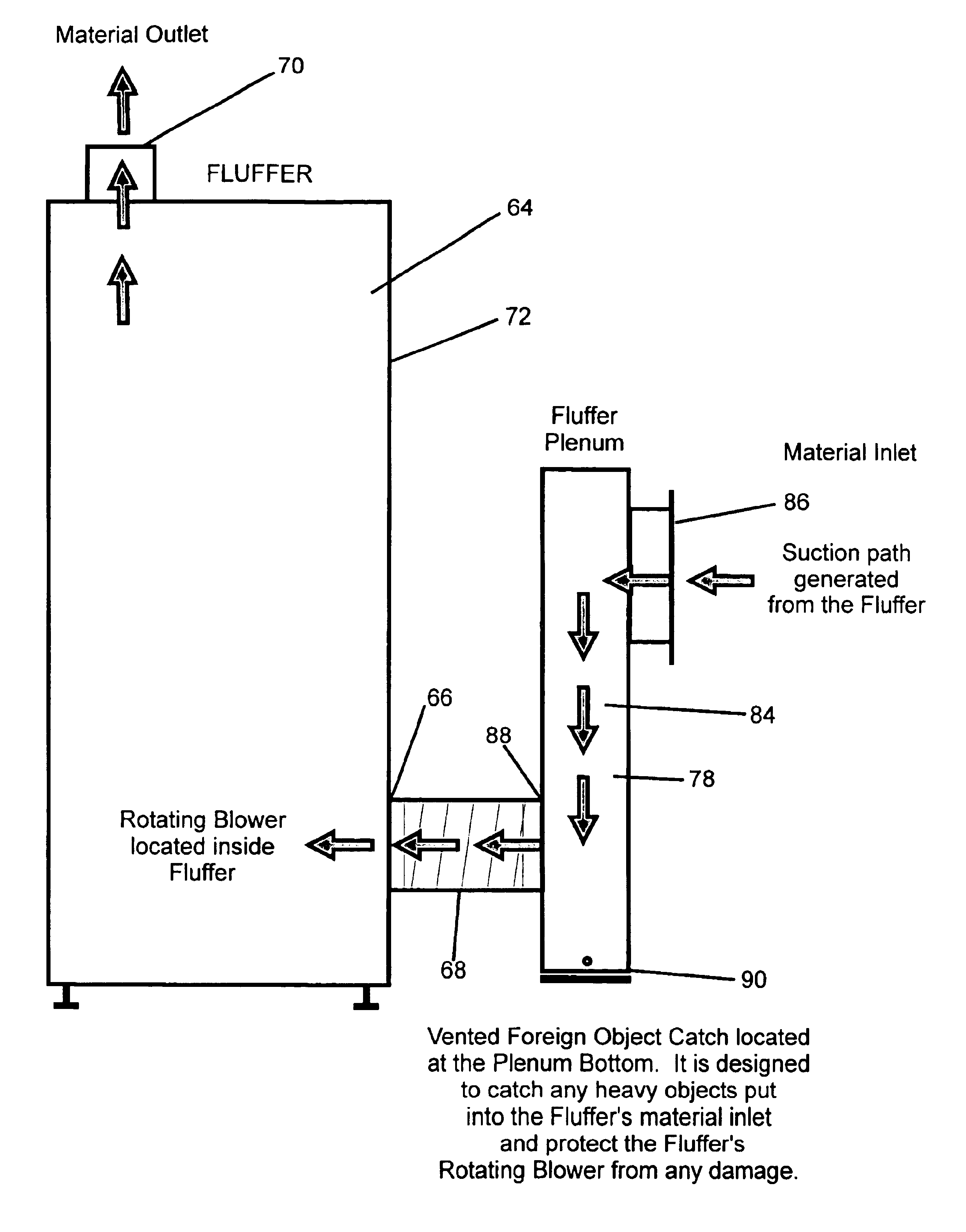
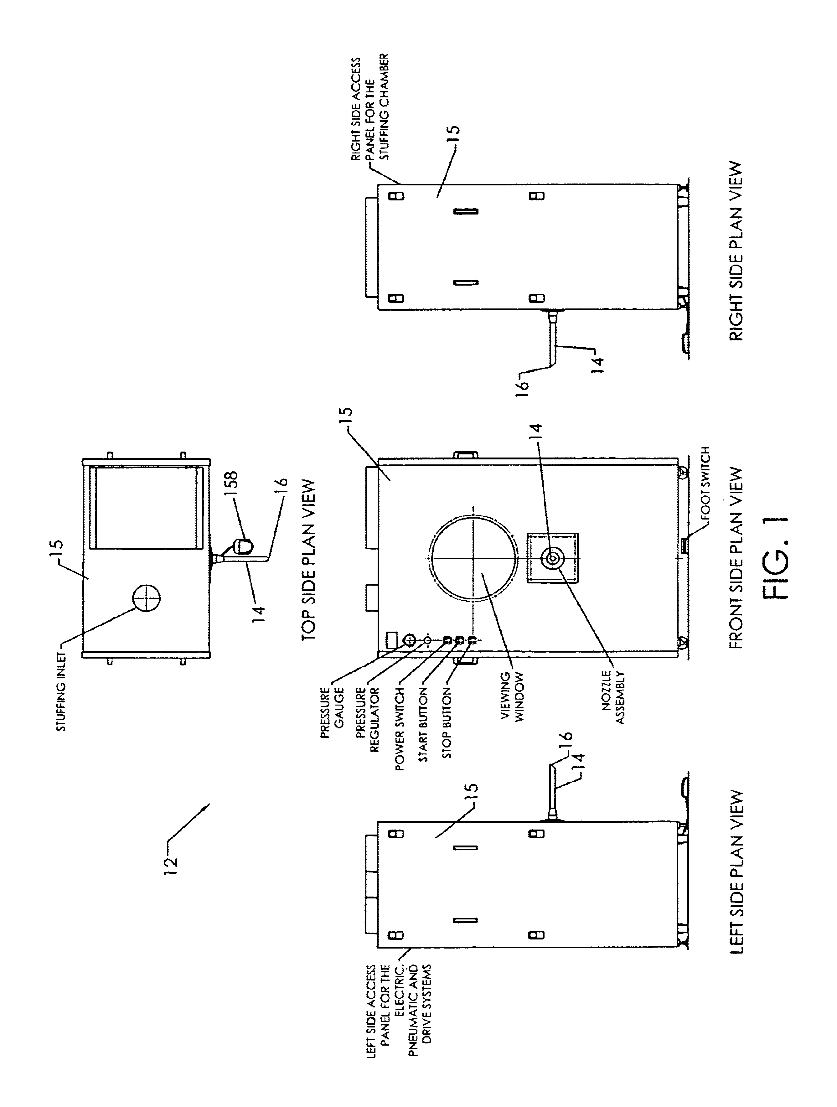
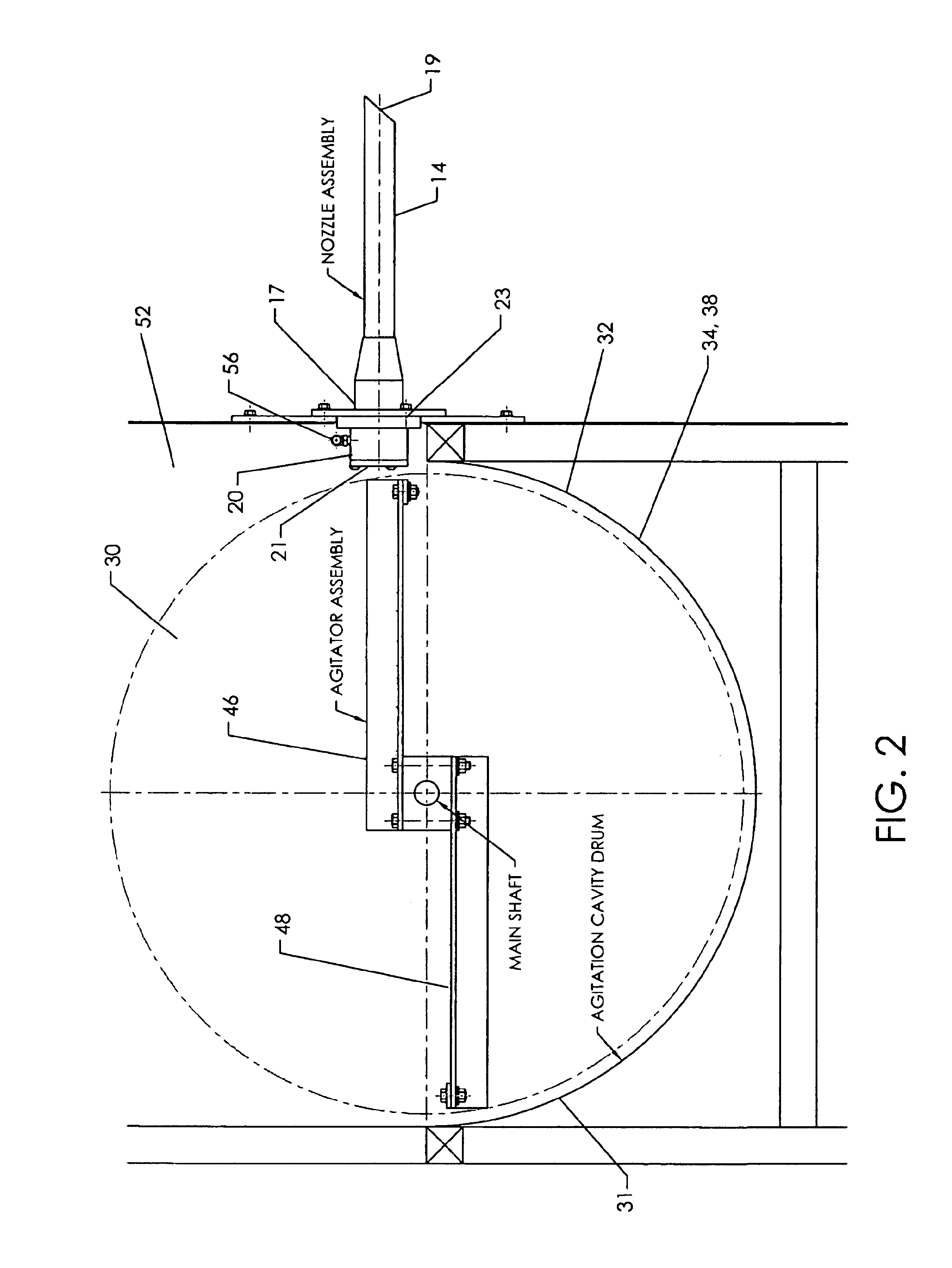
Referring now to the drawings, there is shown in the figures stand alone embodiments of the fiber stuffing and fluffing machine showing the fluffer and stuffer and associated components and circuitry of the present art and integrated embodiments along with associated components and circuitry. The drawings show the fiber stuffing and fluffing machine 10 comprising in an embodiment a stuffing machine 12 having a stuffing nozzle 14, an agitation cavity 30, a control system 50, a pressurized air supply 56, and activation switches 158, 160, 162, 164, and a fluffing machine 64 having a housing 72 and blower 74, a plenum 78, and a blast gate valve 92. All of the aforementioned uniquely formed and combined with further described portions of the apparatus to provide the useful features herein described. An embodiment of the present art combines the stuffing machine 12, fluffing machine 64, and a compressed air source 56 into a single stand alone machine.

The invention first comprises a stuffi...


PUM

PropertyMeasurementUnit
Coloraaaaaaaaaa
Densityaaaaaaaaaa
Electrical conductoraaaaaaaaaa

Abstract

A fiber stuffing and fluffing machine utilized for fiber stuffing toys, pillows, and other skins having a venturi vacuum system, a unique agitation cavity and blade arrangement, and various unique mechanical and electrical features which provide improved stuffing and fluffing capabilities over the prior art. The art of the present invention is capable of integration into a single stand alone unit which performs improved fluffing and stuffing operations without the need for external pneumatic sources. The art of the present invention, in its various embodiments, also utilizes scroll compressors or turbine compressors heretofore not found in prior art stuffing and fluffing applications. The present art further provides means for separating foreign objects from the ingested stuffing fibers to protect the fluffer blower.

Description

BACKGROUND OF THE INVENTIONThe present invention relates in general to stuffing machines and more particularly to a unique fiber stuffing and fluffing machine capable of stuffing pillows, stuffed toys, and other devices, collectively called skins, which comprises unique features not found in the prior art. The present art device utilizes a venturi vacuum system in conjunction with an electric foot switch and air actuated switch and is further fed by a fluffing machine with a unique blast gate valve arrangement. The present art stuffing and fluffing machines are designed in a manner which allows them to be integrated into a single machine along with a compact pneumatic supply.Traditionally stuffing machines comprise at a minimum an output stuffing nozzle tube and an agitation cavity fed by a fiber fluffing machine or picker. Stuffing fibers exit said cavity through a stuffing nozzle. Onto the exiting end of the stuffing nozzle is placed the article to be fiber filled such as the afor...

Claims


Application Information

Patent Timeline
IPC IPC(8): A63H3/02A63H3/00A63H9/00
CPCA63H9/00A63H3/02
Inventor COLLIDA, KARLWOOD, JR., EDWIN T.
Owner COLLIDA KARL
Why Eureka
Try Eureka