
Method and device for low-noise underwater propulsion and for reducing hull drag

a propulsion device and low-noise technology, applied in underwater equipment, special-purpose vessels, vessel construction, etc., can solve the problems of increased noise, increased cost, and increased cost, and achieve the effect of reducing noise and avoiding significant noise emissions

Inactive Publication Date: 2005-03-01
THE BOEING CO
View PDF11 Cites 5 Cited by
  • Summary
  • Abstract
  • Description
  • Claims
  • Application Information

AI Technical Summary

Benefits of technology

The present invention achieves an entirely new method and apparatus for producing propulsion underwater. This method and apparatus is capable of producing propulsion without rotating parts and without significant noise emissions. Furthermore, the invention in its preferred embodiment is capable of propelling a watercraft without opening and closing valves, without using articulating bearings or bushings, without producing significant turbulence, and without any other means that produces an appreciable acoustic emission signature.

Problems solved by technology

However, in some situations, such as in situations involving a watercraft such as a Jet Ski® or a Wave Runner®, an exposed propeller would present significant risk of personal injury, and therefore a ducted propeller is utilized in place thereof.
Although generally less efficient, ducted propellers present significantly less risk of personal injury.
Nonetheless, due to the rotational nature of both exposed propellers and ducted propellers, such propulsion devices inherently produce appreciable acoustic emissions.
Furthermore, the turbulence produced by either type of propeller propulsion also produces detectable acoustic emissions.
This is the case regardless of whether cavitation occurs, albeit cavitation substantially increases the acoustic emissions.
It is also known that the friction between the hull of a watercraft causes a reduction in the momentum of the liquid stream passing adjacent the hull, which results in drag.

Method used


Image

  • Method and device for low-noise underwater propulsion and for reducing hull drag
  • Method and device for low-noise underwater propulsion and for reducing hull drag
  • Method and device for low-noise underwater propulsion and for reducing hull drag

Examples


Embodiment Construction

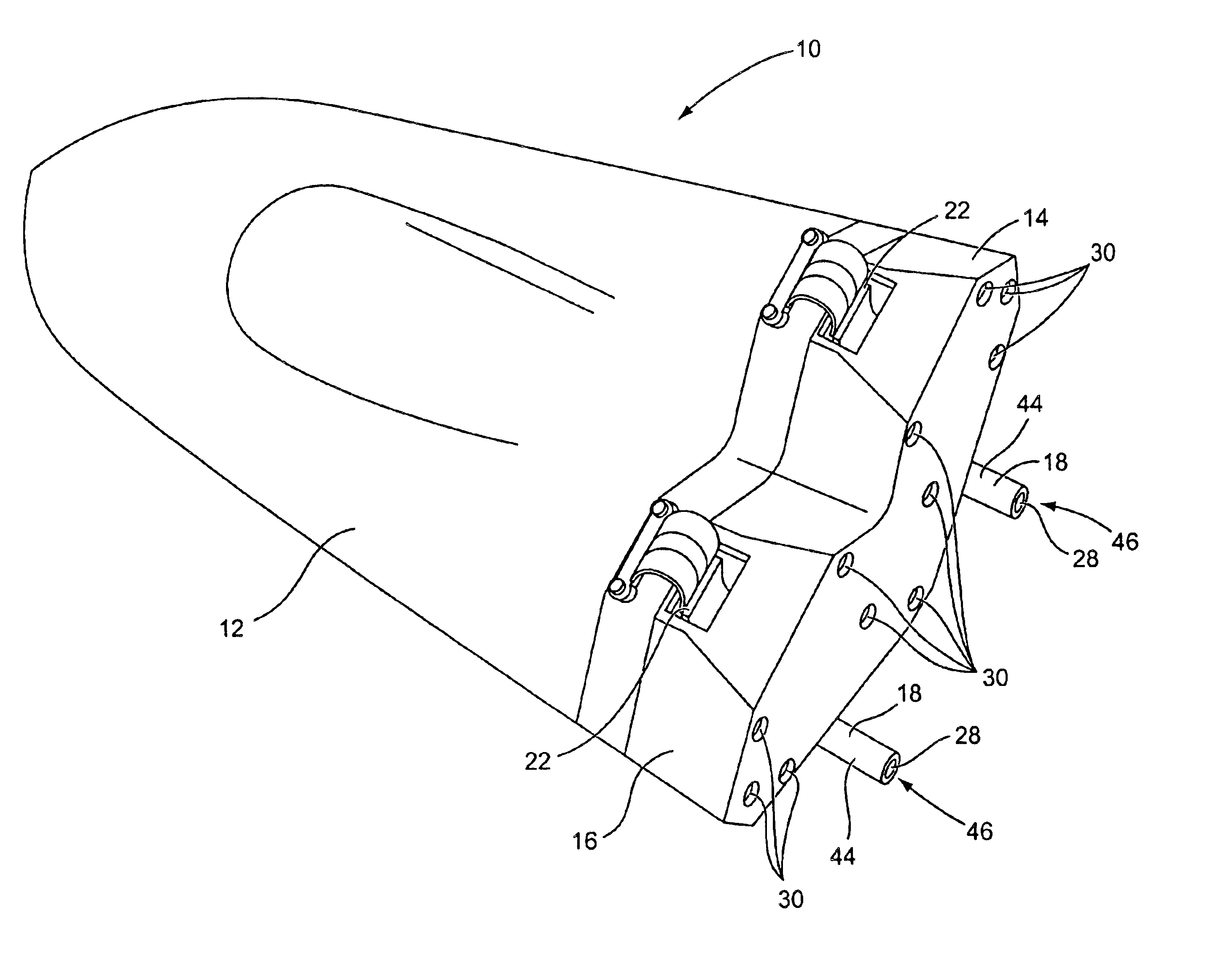
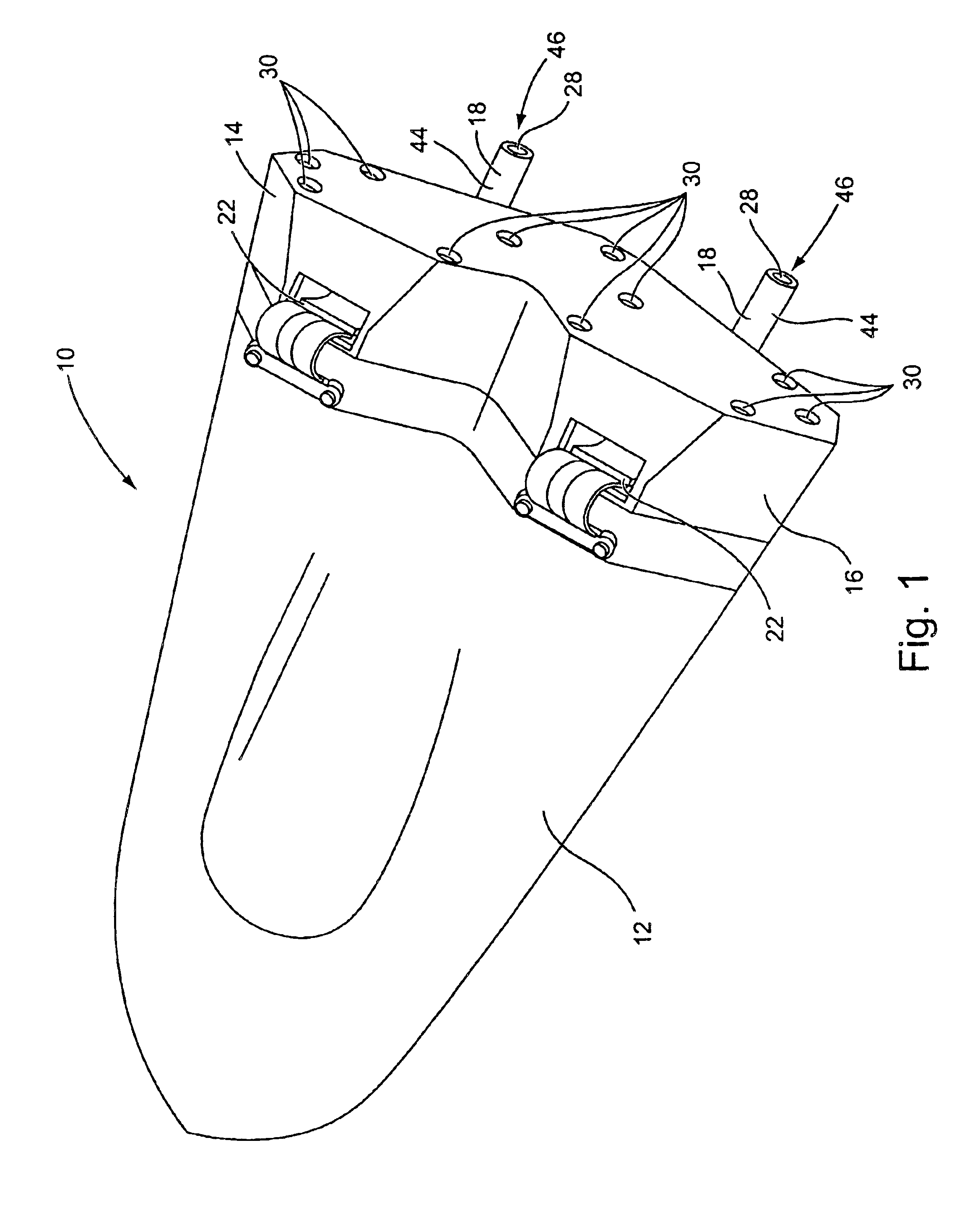
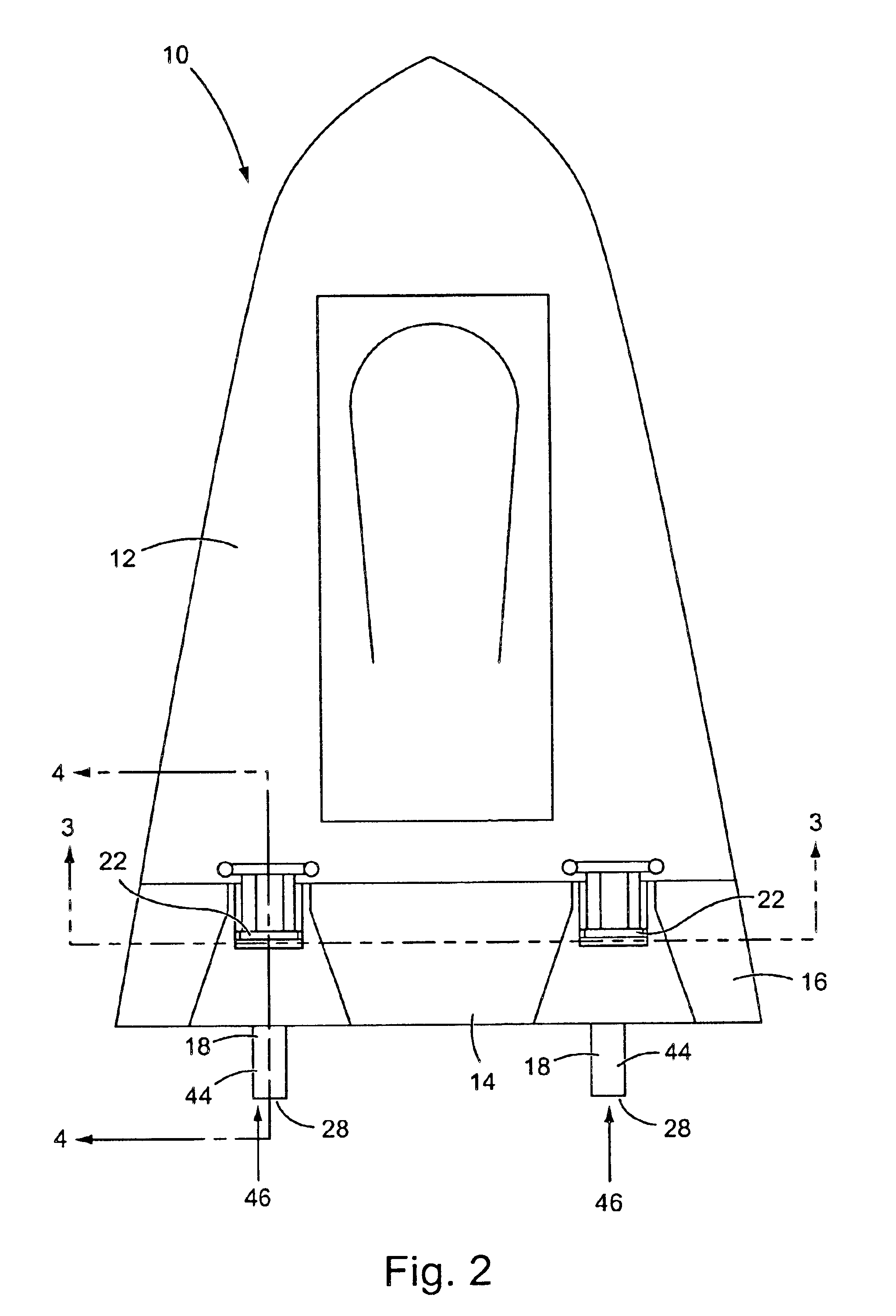
In accordance with the invention, a watercraft has been successfully produced and tested. The watercraft 10 is shown in its entirety in FIGS. 1 and 2 and is configured to float on the surface of a water environment. However, it should be appreciated that the invention could be equally utilized in conjunction with submersible watercraft without undue experimentation or modifications.

In general, the watercraft 10 comprises a main body 12 and an aft propulsion assembly 14. The main body 12 is formed of a composite glass fiber material, but could also be formed of plastic, metal, or other materials suitable for forming watercraft. The main body 12 is also aerodynamically shaped to reduce its drag as it travels through a water or other liquid environment.

The propulsion assembly 14 comprises a housing member 16 and two propulsion generating sub-assemblies 18. The propulsion generating sub-assemblies 18 are preferably identical to each other and each preferably comprises an electromagnetic...


PUM


Abstract

A method and apparatus is disclosed for producing propulsion underwater with minimal acoustical emission. In basic concept, the method comprises the expulsion and sucking of liquid into and out of a liquid port of a watercraft in a manner generating compression and expansion waves adjacent the liquid port. Such expansion and compression waves generate a positive net thrust on the watercraft in a direction opposite that of their expulsion. Also disclosed is a method and apparatus for reducing the drag caused by hull skin friction by actively increasing the momentum of the liquid stream boundary layer adjacent a watercraft via the expulsion of fluid (liquid or gas) from ports in the hull of such a watercraft.

Description

BACKGROUND OF THE INVENTIONVarious types of propulsion devices are known for propelling watercraft through water environments. Such types of propulsive devices include types that push water, push air, and that are propelled by other means, such as by rocket. This invention pertains particularly to water pushing propulsion devices.Various types of water pushing devices have clearly been proven successful and have been utilized for decades and even centuries. Presently, the most common of such devices in use are the exposed rotating propeller and the ducted rotating propeller (the later often being referred to as “jet” propulsion). In most circumstances, the exposed type of propeller is the most efficient and practical means for powering a watercraft. However, in some situations, such as in situations involving a watercraft such as a Jet Ski® or a Wave Runner®, an exposed propeller would present significant risk of personal injury, and therefore a ducted propeller is utilized in place...

Claims


Application Information

Patent Timeline
Patent Type & Authority Patents(United States)
IPC IPC(8): B63H11/00B63H11/06F04B17/03F04B17/04
CPCF04B17/044B63H11/06B63G2013/022
Inventor HASSAN, AHMED A.DOMZALSKI, DAVID B.
Owner THE BOEING CO
Learn More