

Heating device and fixing device
a heating device and fixing device technology, applied in the direction of electric/magnetic/electromagnetic heating, electrographic process, instruments, etc., can solve the problems of limiting the density of coil winding in cross section, no method or solution in order to execute fine temperature control, and general skin effect of the wire for the coil used in the induction heating device. achieve the effect of improving the density of coil winding
- Summary
- Abstract
- Description
- Claims
- Application Information
AI Technical Summary
Benefits of technology
Problems solved by technology
Method used
Image

Examples
first embodiment
To begin with, the invention is described.
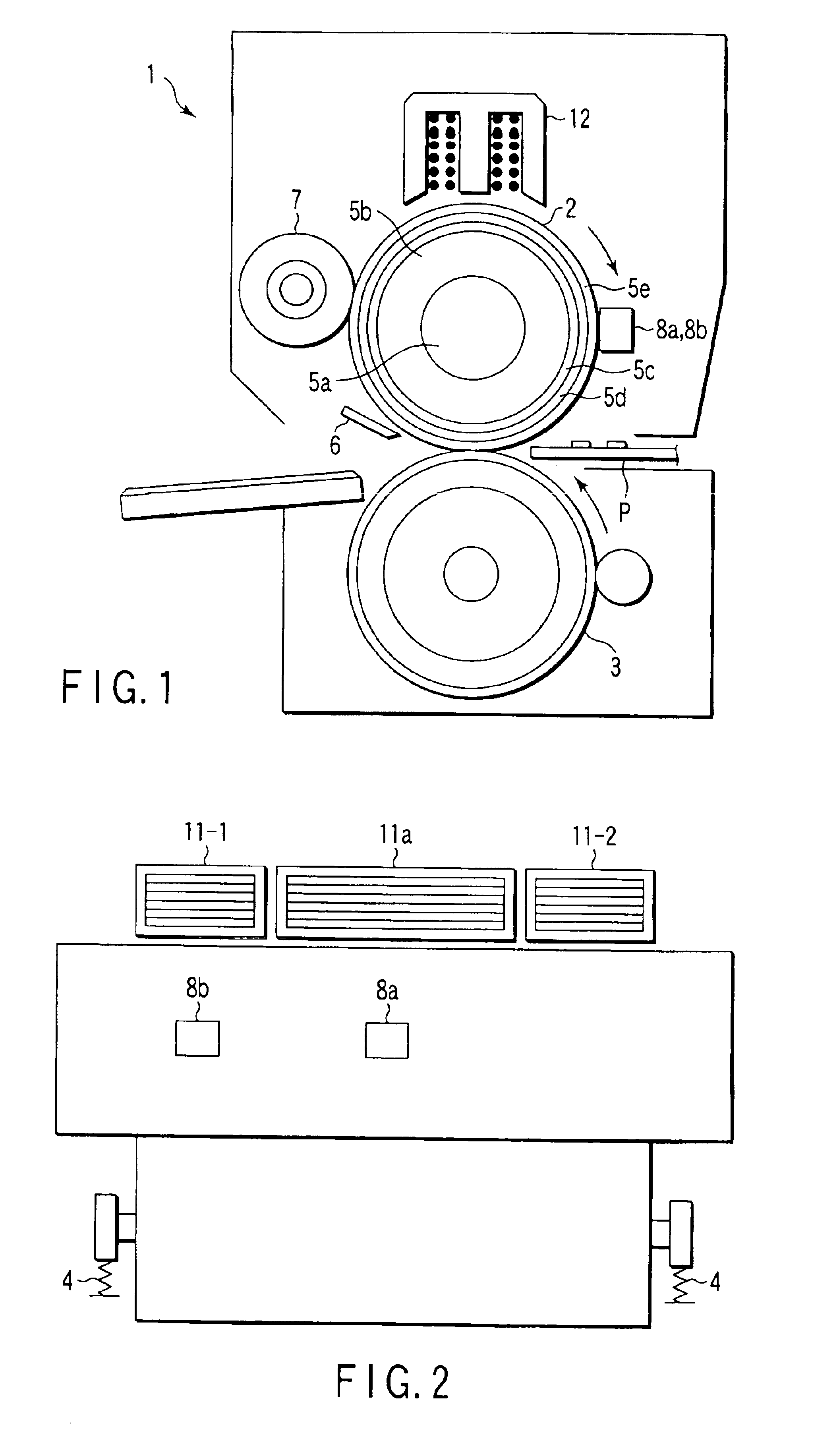
FIG. 1 shows the whole structure of a fixing device 1 used in an image forming apparatus.
FIG. 2 is a diagram showing the fixing device 1 in its longitudinal direction.
The fixing device 1 includes a heating roller 2 (φ40 mm) and a press roller 3 (φ40 mm). The heating roller 2 is driven by a drive motor (not shown) in a direction of the arrow, and the press roller 3 rotates following the rotation of the heating roller 2 in a direction of the arrow. The press roller 3 is put in pressure contact with the heating roller 2 by a pressing mechanism 4 so that a predetermined nip width is provided between the rollers 3 and 2.
The heating roller 2 comprises a metal core 5a, foamed rubber (sponge) 5b, a metal conductive layer 5c, a solid rubber layer 5d, and a release layer 5e in the named order from the inside.
In the present embodiment, the thickness of the foamed rubber is 5 mm and nickel is used as the material of the metal conductive layer.
In this em...
second embodiment
the invention will now be described.
A fixing device according to the second embodiment has the same structure as the fixing device 1 of the first embodiment shown in FIG. 1. The difference is that the wire used for the excitation coils is not the litz wire but a single wire. The number of turns of winding is unchanged. The diameter of the wire is φ1 mm.
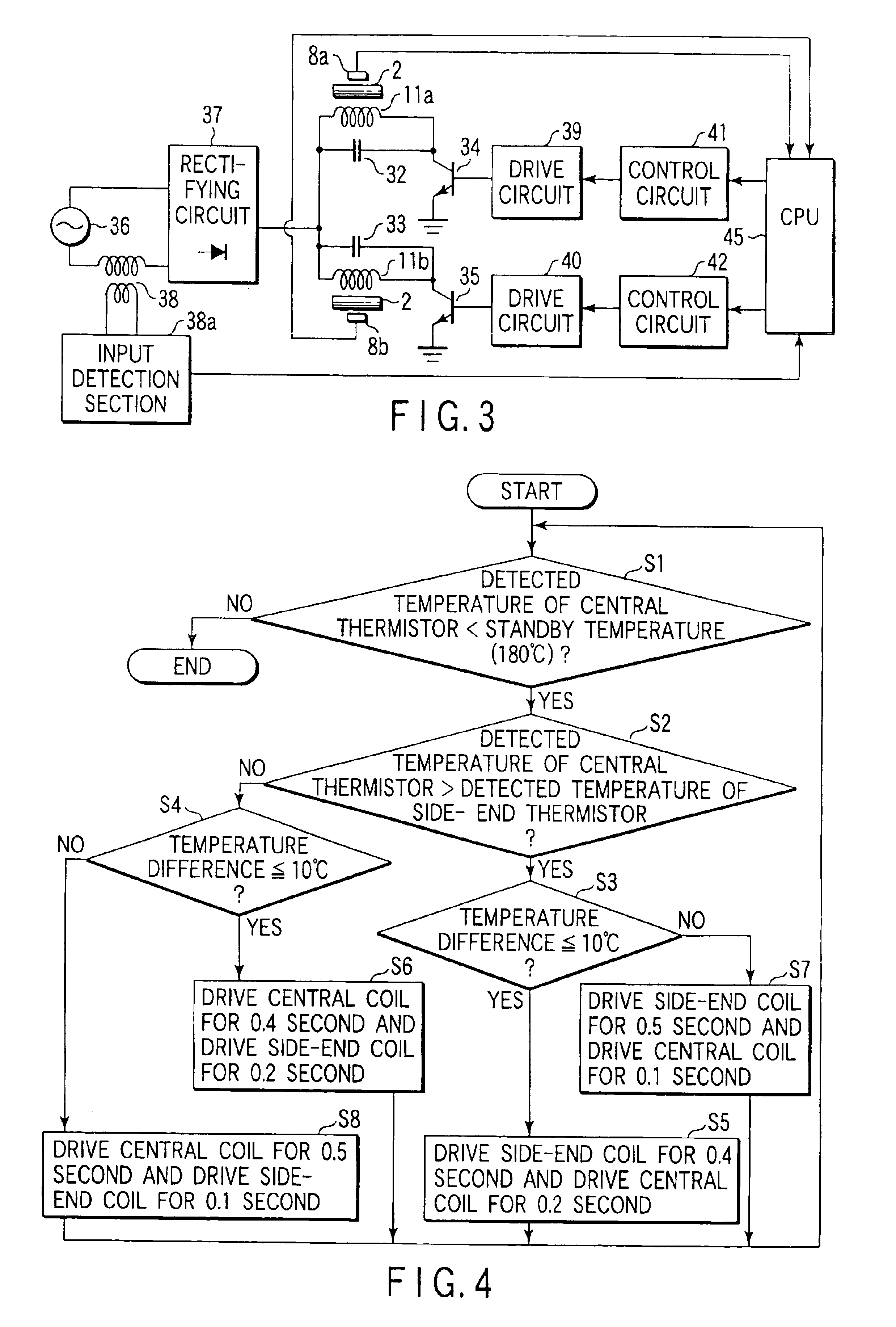
FIG. 7 is a block diagram showing an electrical construction relating to temperature detection and a method of controlling excitation coils and an oscillation circuit (inverter circuit).
The difference from the first embodiment is that there are provided a single switching element 60, a single drive circuit 61 and a single control circuit 62. Excitation coils 63A and 63B corresponding to the central coil 11a and side-end coil 11b are connected in parallel. Resonance circuits are constructed by the excitation coil 63A and a capacitor 64 and by the excitation coil 63B and a capacitor 65, respectively.
In this embodiment, the operational f...
third embodiment
the invention will now be described.
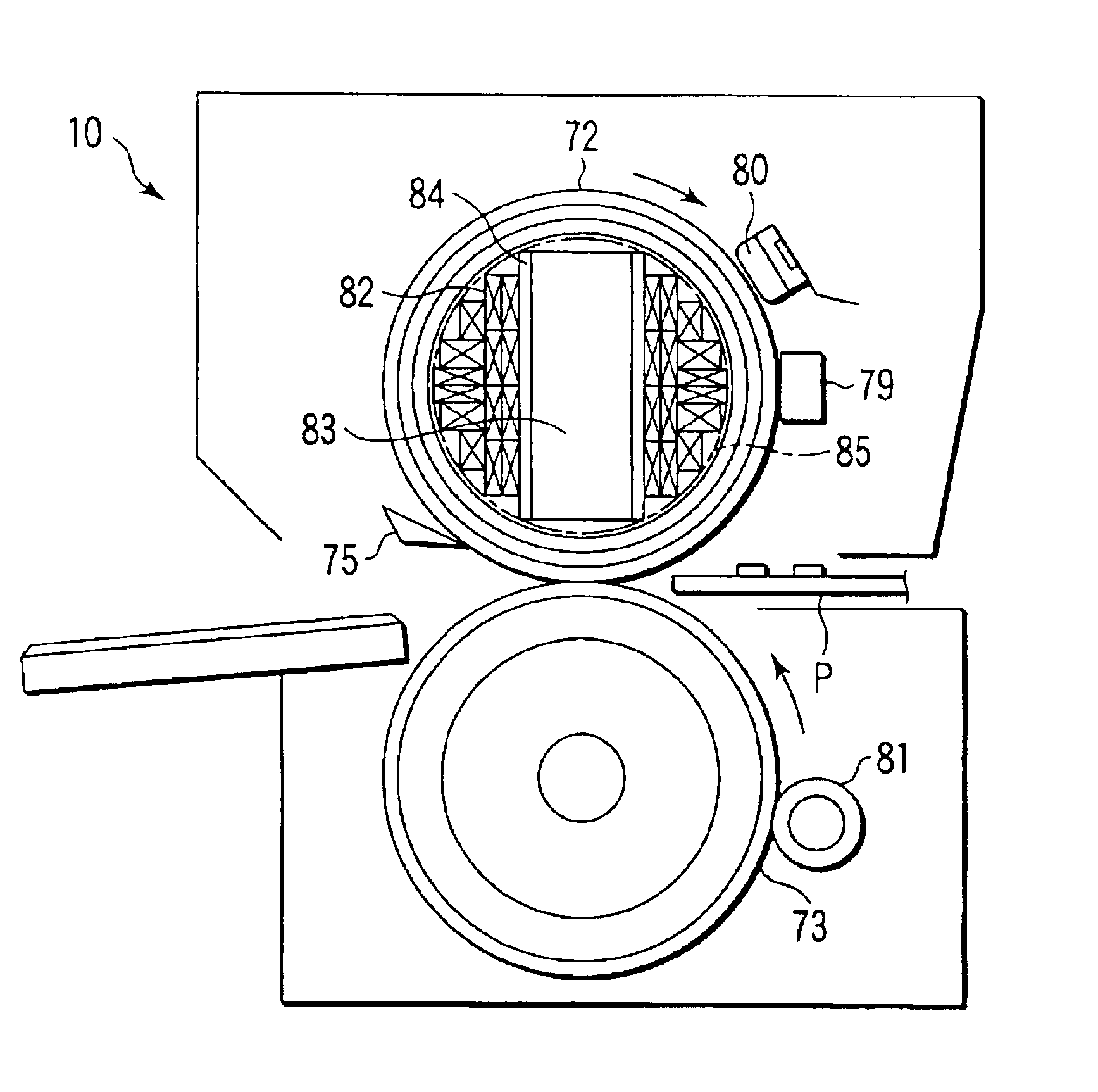
FIG. 8 is a schematic cross-sectional view showing the whole structure of a fixing device 10 according to the third embodiment.
The fixing device 10 includes a heating (fixing) roller 72 (φ40 mm) and a press roller 73 (φ40 mm). The heating roller 72 is driven by a drive motor (not shown) in a direction of the arrow, and the press roller 73 rotates following the rotation of the heating roller 72 in a direction of the arrow. The press roller 73 is put in pressure contact with the heating roller 72 by a pressing mechanism so that a predetermined nip width is provided between the rollers 73 and 72.
The heating roller 72 is formed of iron, with a wall thickness of 1 mm. A release layer of, e.g. Teflon, is coated on the surface of the heating roller 72. In this embodiment, iron is used as the material of the roller. Alternatively, stainless steel, aluminum or a composite of stainless steel and aluminum may be used.
The press roller 73 is constructed such t...
PUM
 Abstract
Description
Claims
Application Information