Variable refresh control for a memory

Inactive Publication Date: 2005-03-01
NXP USA INC
View PDF15 Cites 86 Cited by
  • Summary
  • Abstract
  • Description
  • Claims
  • Application Information

AI Technical Summary

Problems solved by technology

The periodic refresh operation requires a significant amount of power.
Also, process variations can cause greater leakage.
A fi

Method used


Image

  • Variable refresh control for a memory
  • Variable refresh control for a memory
  • Variable refresh control for a memory

Examples


Example

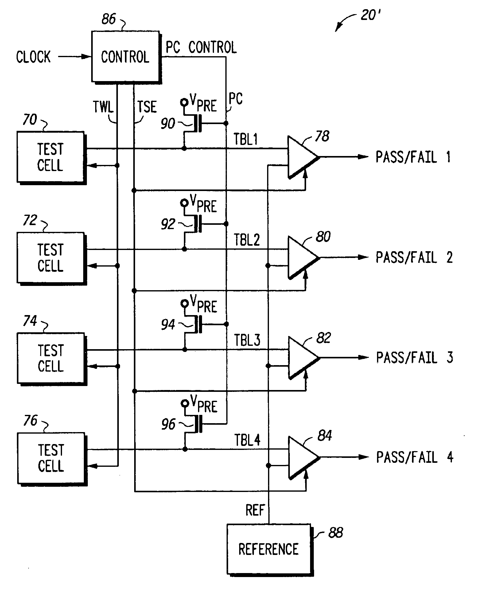
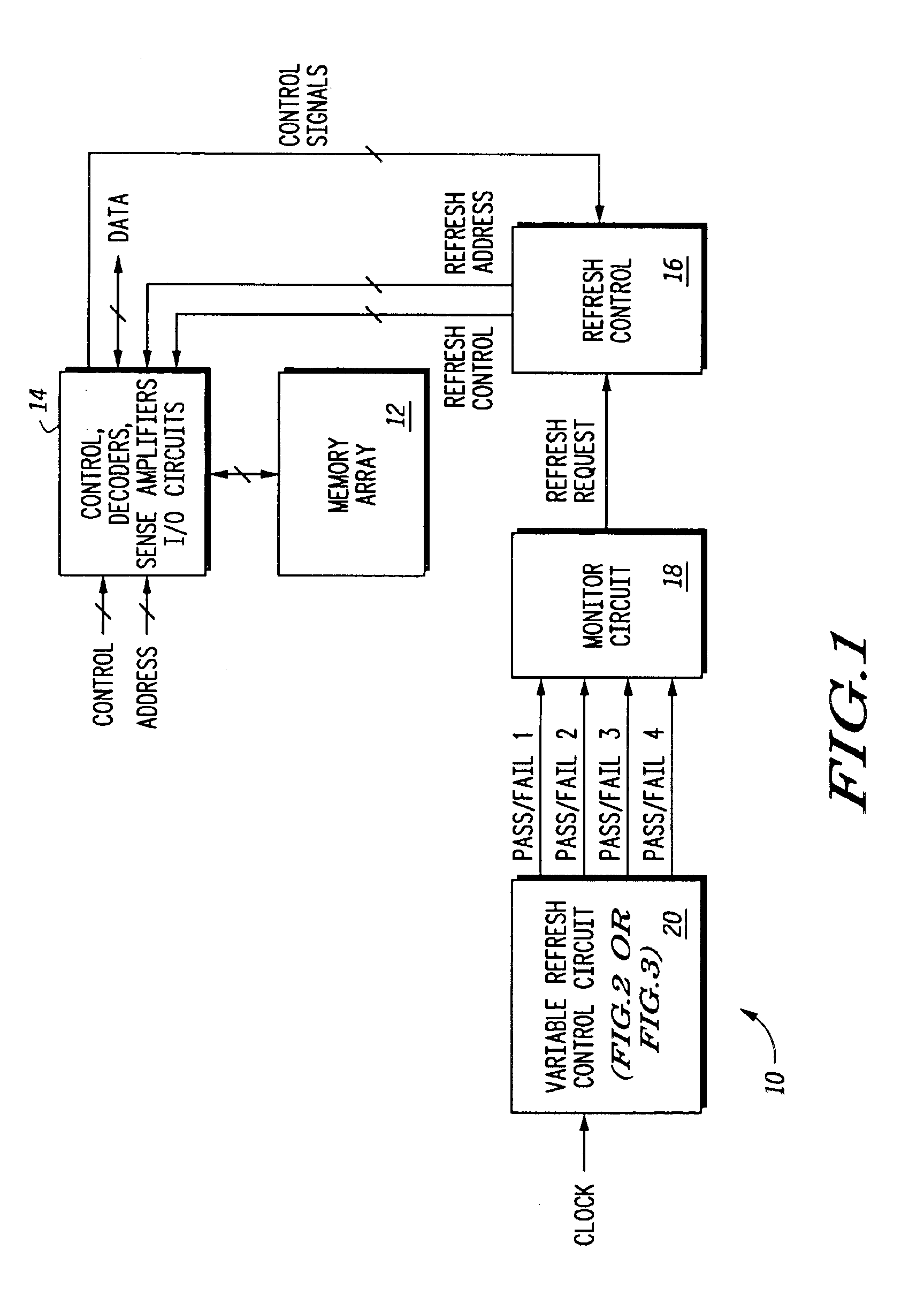
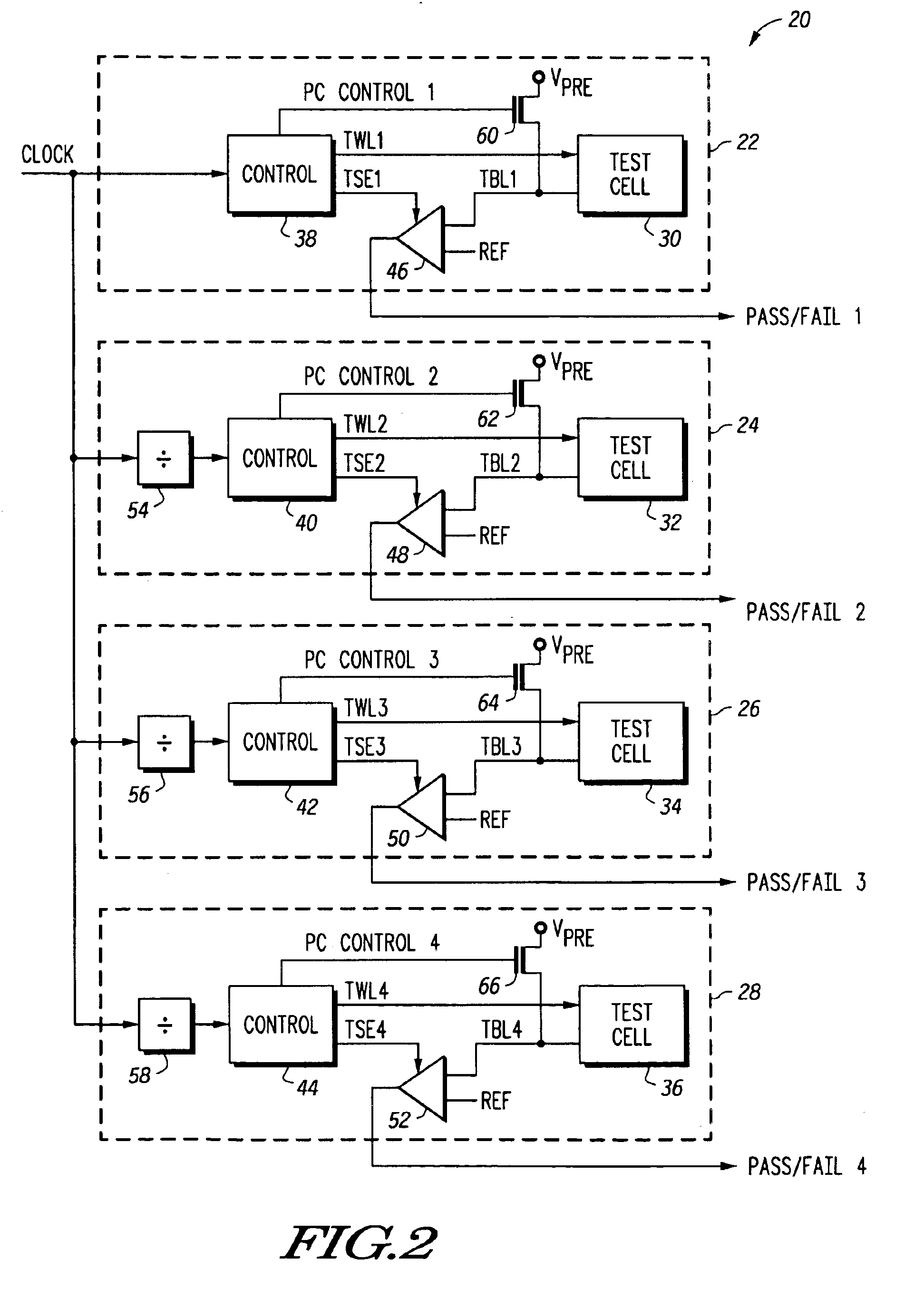
Generally, the present invention provides a memory having a variable refresh control circuit that includes a plurality of test memory cells to determine an optimum refresh rate for the memory that gives reliable performance and lower power consumption. The variable refresh control circuit includes a plurality of test memory cells. In one embodiment, each of a plurality of substantially identical test memory cells includes a capacitor for storing charge representative of a stored logic state, and each of the plurality of test memory cells is refreshed at a different rate than other test memory cells. A monitor circuit is provided for monitoring the stored logic state of each of the plurality of test memory cells, and in response, a refresh rate of the plurality of memory cells is adjusted.

In another embodiment of the present invention, the variable refresh control circuit includes a plurality of test memory cells, where each of the test memory cells includes a different sized capacit...


PUM


Abstract

A memory (10) includes a variable refresh control circuit (20) for controlling the refresh rate of a memory array (12) using a capacitor for data storage. In one embodiment, each test cell of a plurality of test memory cells (30, 32, 34, and 36) is refreshed at different rates. A monitor circuit (18) is provided for monitoring the stored logic state of each of the plurality of test memory cells, and in response, adjusting the refresh rate of the memory array (12). In another embodiment, a variable refresh control circuit (20′) includes a plurality of test memory cells (70, 72, 74, and 76) that are all refreshed at the same rate but each of the test memory cells (70, 72, 74, and 76) is implemented to have a different charge storage capacity than the other test memory cells. The monitor circuit (18) monitors the stored logic state of each of the plurality of test memory cells (70, 72, 74, and 76), and in response, adjusts a refresh rate of the memory array (12).

Description

FIELD OF THE INVENTIONThis invention relates generally to integrated circuit memories, and more particularly to a variable refresh control for a dynamic random access memory (DRAM).BACKGROUND OF THE INVENTIONA dynamic random access memory (DRAM) is a well known memory type that depends on a capacitor to store charge representative of two logic states. Generally, each DRAM cell includes a capacitor and an access transistor. The charge stored on the capacitor leaks away over time, requiring the data stored by DRAM cells to be periodically read and rewritten, or “refreshed”. The periodic refresh operation requires a significant amount of power.The amount of charge leakage from the capacitors varies greatly depending on voltage, temperature and process variations. A higher temperature or voltage causes greater leakage than a relatively lower temperature or voltage. Also, process variations can cause greater leakage. Therefore, for DRAMs having a fixed refresh rate, the memory cells must...

Claims


Application Information

Patent Timeline
IPC IPC(8): G11C11/406G11C29/02
CPCG11C11/406G11C29/02G11C29/50012G11C29/50016G11C29/028G11C11/401G11C2211/4061G11C11/4091
Inventor BURGAN, JOHN M.
Owner NXP USA INC
Why Eureka
Try Eureka