Transmitter filter arrangement for multiband mobile phone

Active Publication Date: 2005-03-01
AVAGO TECH INT SALES PTE LTD
View PDF6 Cites 79 Cited by
  • Summary
  • Abstract
  • Description
  • Claims
  • Application Information

AI Technical Summary

Benefits of technology

It is a primary object of the present invention to provide in a transmitter module a filter having a good attenuation at a certain frequency and, more particularly, at the W-CDMA receive frequency and a small attenuation at the W-CDMA transmit frequency. This object can be achieved by disposing an acoustic-wave filter comprising one or more L-sections

Problems solved by technology

In general, it is difficult to achieve a device of high resonance frequency using this fabrication method.
The disadvantages of the membrane type approach are that it is difficult to produce the layers 507, 509, 511 on top of the membrane 505 so that they have sufficiently small mechanical stress, which would break or bend the membrane 505.
Moreover, the membrane structure is not very rugged m

Method used


Image

  • Transmitter filter arrangement for multiband mobile phone
  • Transmitter filter arrangement for multiband mobile phone
  • Transmitter filter arrangement for multiband mobile phone

Examples


Example

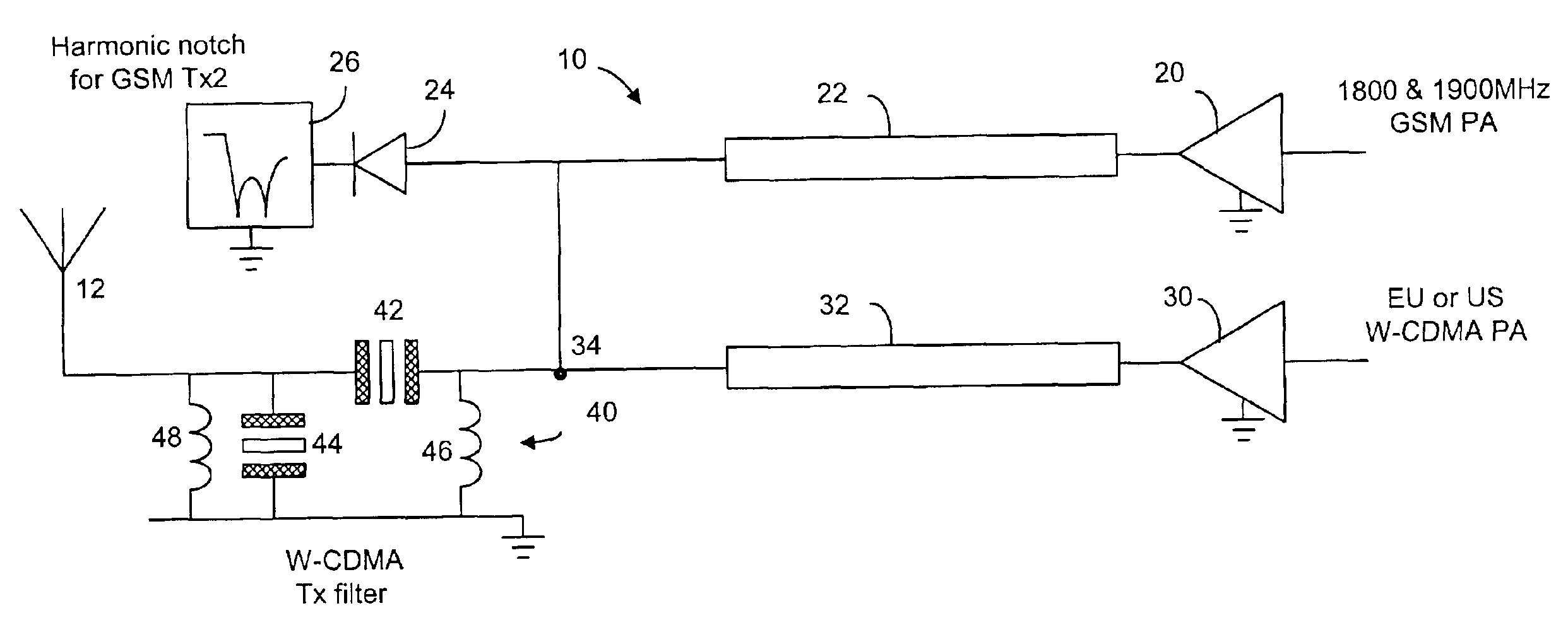
In a multiband mobile terminal operating both in W-CDMA mode and in GSM mode, currently the front end is arranged to have two separate antennas, one for the W-CDMA frequency band and one for the GSM frequency bands. In the GSM mode, the transmitter and the receiver are separated by switching. In the W-CDMA mode, a duplexer or a diplexer is used. The present invention combines bandpass and band-reject filters using acoustic-wave resonators. The combined filter can be made to have a very deep notch at the W-CDMA receive frequency, while retaining wide passband (at least 30 MHz) with very low loss. The combined filter is shown as a band-reject filter 40 in FIGS. 8, 11 and 12. In particular, the combined filter is used in a front-end of a multiband, dual-mode mobile terminal (GSM+W-CDMA), as shown in FIGS. 8 and 11. The front-end is used herein to refer to the RF (radio frequency) parts that are disposed between a typical RF-asic(s) and an antenna. The front-end has a transmitter module...


PUM


Abstract

A filter arrangement for use in a multiband dual-mode mobile phone. In particular, the mobile phone is operable in a W-CDMA mode and a band-reject filter comprising at least a series and a shunt acoustic-wave resonators is used to create a deep notch at the receive frequency band. The band-reject filter further includes a plurality of inductive elements for matching static capacitance of the resonators at the passband frequency. The mobile phone is also operable in 1800 and 1900 GSM bands. The band-reject filter is operatively connected to a harmonic trap in order to eliminate the third harmonic of these GSM bands. The mobile phone is also operable in the lower GSM band, for which a harmonic filter can share an antenna path with the band-reject filter.

Description

FIELD OF THE INVENTIONThe present invention relates generally to thin-film bulk acoustic wave filters and, more particularly, to bulk acoustic wave filters in mobile phone front-end.BACKGROUND OF THE INVENTIONIt is known that a bulk acoustic-wave (BAW) device is, in general, comprised of a piezoelectric layer sandwiched between two electronically conductive layers that serve as electrodes. When a radio frequency (RF) signal is applied across the device, it produces a mechanical wave in the piezoelectric layer. The fundamental resonance occurs when the wavelength of the mechanical wave is about twice the thickness of the piezoelectric layer. Although the resonant frequency of a BAW device also depends on other factors, the thickness of the piezoelectric layer is the predominant factor in determining the resonant frequency. As the thickness of the piezoelectric layer is reduced, the resonance frequency is increased. BAW devices have traditionally been fabricated on sheets of quartz cr...

Claims


Application Information

Patent Timeline
IPC IPC(8): H04B1/40H04B5/00
CPCH03H9/542H03H9/706H04B5/0075H04B1/005H04B1/006H04B1/406H03H2007/013H03H2011/0488H03H2250/00H04B1/10H04B1/04H04B7/00H04B15/00
Inventor ELLA, JUHA
Owner AVAGO TECH INT SALES PTE LTD
Why Eureka
Try Eureka