Process and system for recovering energy from carbon-containing materials
a technology of carbon-containing materials and processes, applied in the direction of gasification process details, gas purification by non-gaseous material condensation, combustion process, etc., can solve the problems of increasing the quantity of waste materials of various kinds, and increasing the quantity of waste materials
- Summary
- Abstract
- Description
- Claims
- Application Information
AI Technical Summary
Benefits of technology
Problems solved by technology
Method used
Image
Examples
third embodiment
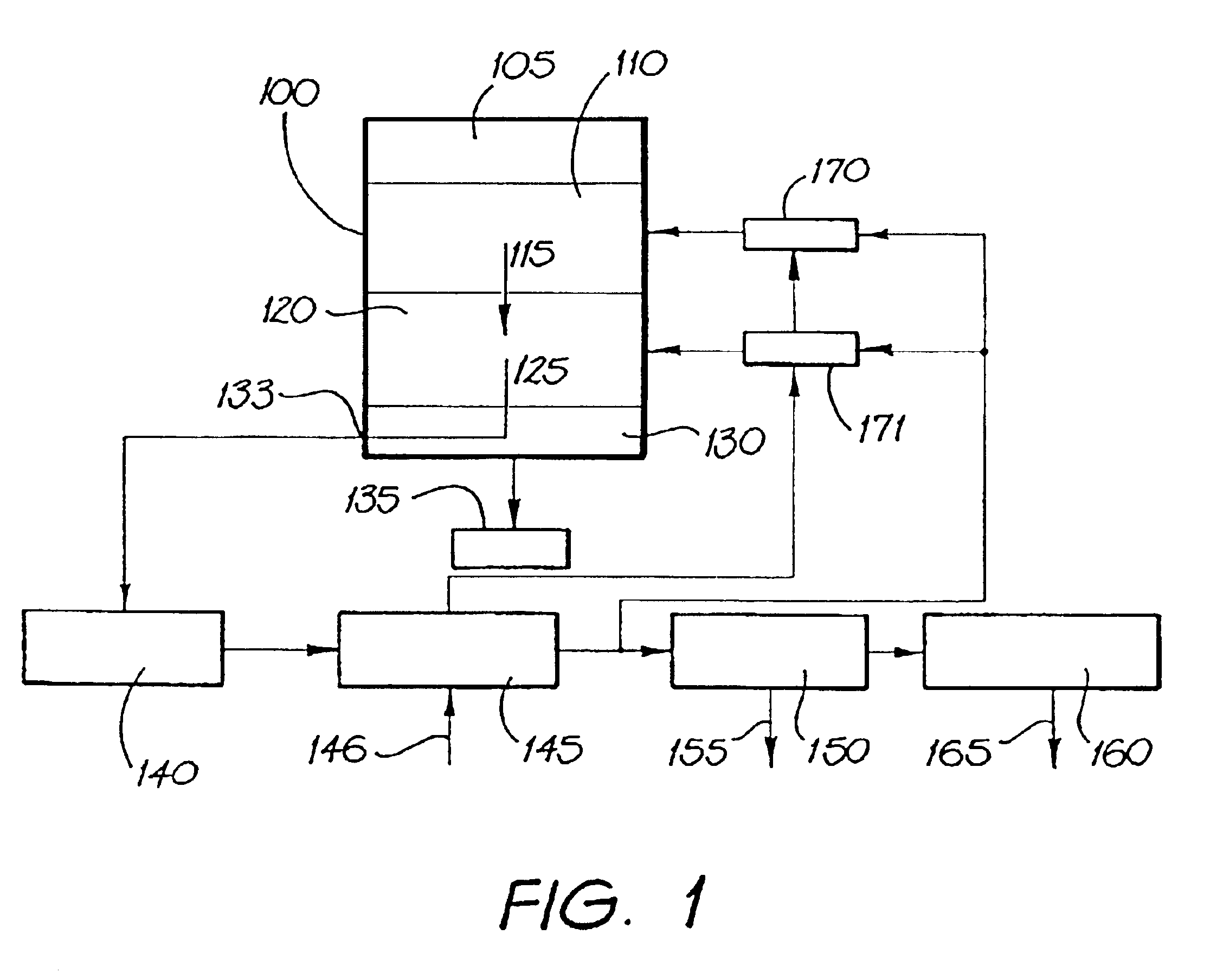
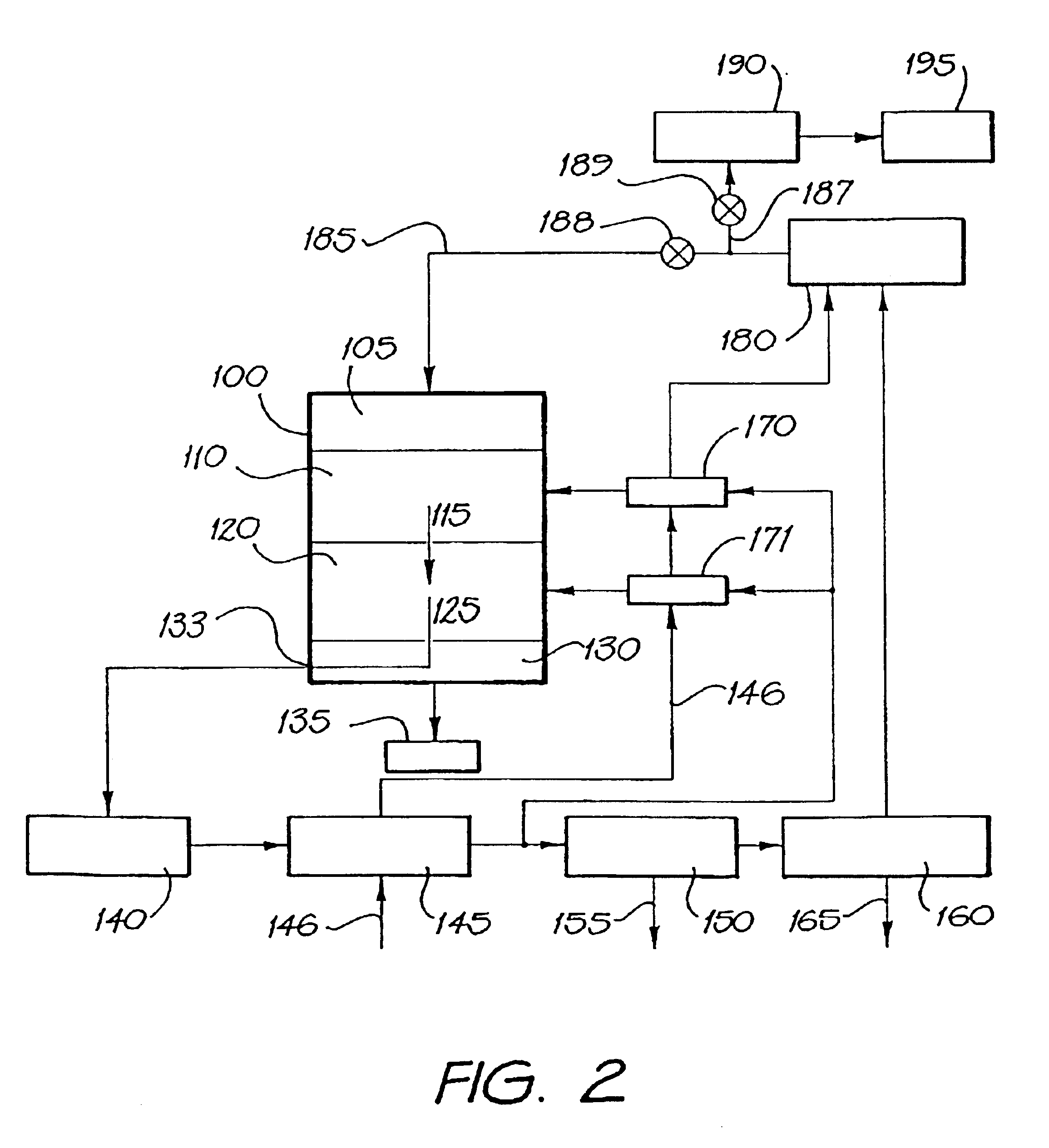
In one form of the process of the third embodiment, at least part of the vapour phase from the pyrolysis zone is removed from the reactor and a portion of it is burned to generate at least part of the heat necessary to maintain the first and / or second elevated temperatures. In this form, part or all of the combustion products generated by burning the vapour phase removed from the pyrolysis zone is provided to the reaction zone to provide at least part of the water vapour required for step (b).
In another form of the process of the third embodiment step (c) consists of burning a first part of a mixture of the first gaseous product and the second gaseous product. Typically, in this form of the process the combustion products of step (c) are returned to the reactor such that they must pass through the carbon-enriched solid in the reaction zone before leaving the reactor. Usually in this form of the process of the third embodiment, the first part of the mixture of first gaseous product a...
second embodiment
Hence, if sufficient steam is available and carbon monoxide is removed from the reaction zone, carbon in the carbon-enriched solid tends to be consumed and converted into oxides of carbon. Further charring / coking of the carbon-enriched solid may also occur in the reaction zone. Advantageously, however, carbon monoxide is permitted to accumulate in the reactor by recycling to the reactor all combustion products after burning the first and second gaseous products, as in the process of the
In another form of the processes of the invention, gases produced in the reactor may be removed from the reactor and at least part of the carbon dioxide and carbon monoxide may be at least partially separated from hydrogen by conventional means. In this form, the separated carbon monoxide and carbon dioxide (which may also contain some nitrogen) are typically combusted and the combustion products are returned to the interior of the reactor, typically the reaction zone.
Typically, the water vapour or st...
example
The following is a description of laboratory scale trials of a process in accordance with the invention.
Apparatus
The reactor was constructed as in FIG. 4 with schedule 40 pipe and 8 mm plate. In FIG. 4. FIG. 4A is a vertical cross-sectional view of die reactor, FIG. 4B is a plan view of the reactor, and FIG. 4C is a diagrammatic representation of the relative position of gas offtake points from the reactor. Legs, bracing and footings were constructed from 3×3×0.25-inch (75×75×6.4 mm) angle section. All flanges and blanks were ANSI 300 lb (2070 kPa) fittings. The lid to the reactor, a 24″ (600 mm) flange & blank (ANSI-300 lb (2070 kPa)) was fitted with pressure relief valve set at 100 psi (689 kPa) and pressure gauge. It was also fitted with a 2.5″ (64 mm) flanged stub and ball valve to allow access of a steel, graduated dipstick.
As seen in FIGS. 4 and 5, the reactor consists of a firebox 400 surrounding the upper part of the reactor body 450 which consists of an annular space 410 de...
PUM
 Abstract
Description
Claims
Application Information
 - R&D
- Intellectual Property
- Life Sciences
- Materials
- Tech Scout
- Unparalleled Data Quality
- Higher Quality Content
- 60% Fewer Hallucinations
Browse by: Latest US Patents, China's latest patents, Technical Efficacy Thesaurus, Application Domain, Technology Topic, Popular Technical Reports.
© 2025 PatSnap. All rights reserved.Legal|Privacy policy|Modern Slavery Act Transparency Statement|Sitemap|About US| Contact US: help@patsnap.com


