Crossflow air heater bypass

Inactive Publication Date: 2005-03-08
PPL
View PDF2 Cites 8 Cited by
  • Summary
  • Abstract
  • Description
  • Claims
  • Application Information

AI Technical Summary

Benefits of technology

Accordingly, the present invention advantageously emulates an air heater bypass. In some instances, it is not even necessary to retrofit an existing boiler system with new ductwork to achieve advantages of the present invention. The present invention advantageously increases flue gas temperatures, which in turn reduces condensation, including sulfuric acid mist in the flue gas and along the path of the flue gas. The reduction in condensation reduces corrosion and thereby prolongs the life of the boiler system, and in particular, the portions of the boiler system that are most susceptible to corrosion caused by acid condensation. The reduction in acid mist also causes a corresponding reduction in the opacity of the flue gas in the lower portions of the stack. Thus, sensors or other devices for measuring opacity will not be affected by the acid mist and therefore will not incorrectly detect the acid mist as particulate waste.
Additionally, the presen

Problems solved by technology

The reduction in condensation reduces corrosion and thereby prolongs the life of the boiler system, and in par

Method used


Image

  • Crossflow air heater bypass
  • Crossflow air heater bypass
  • Crossflow air heater bypass

Examples


Example

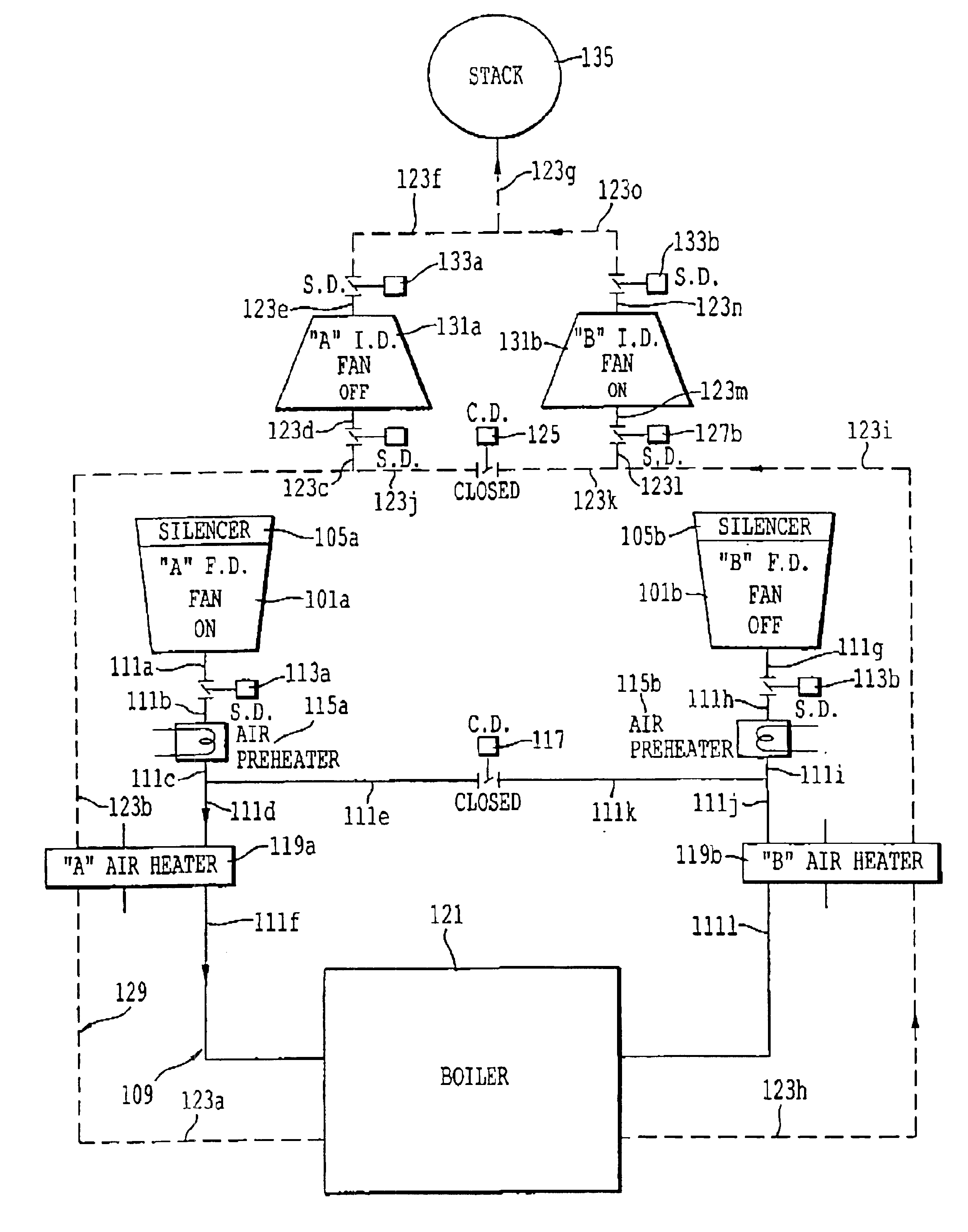
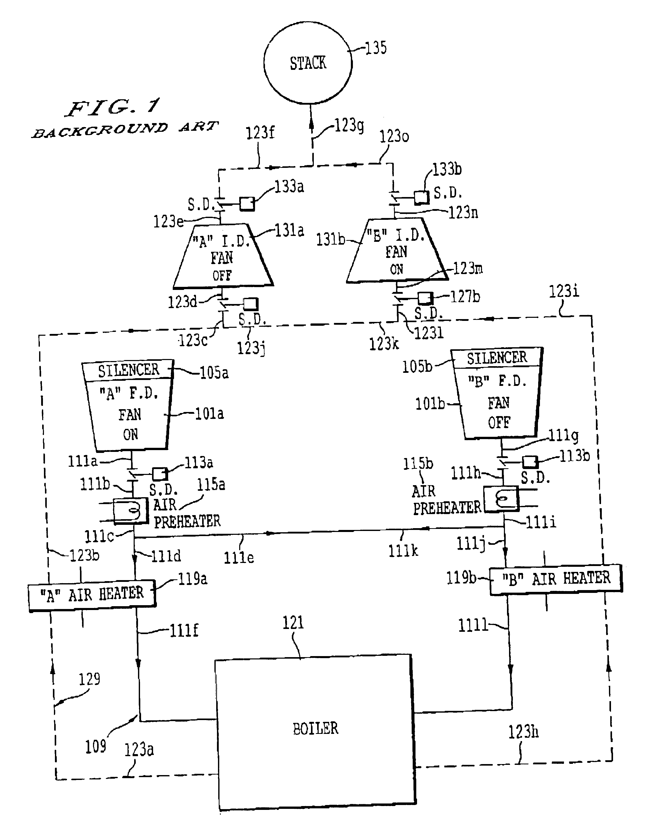
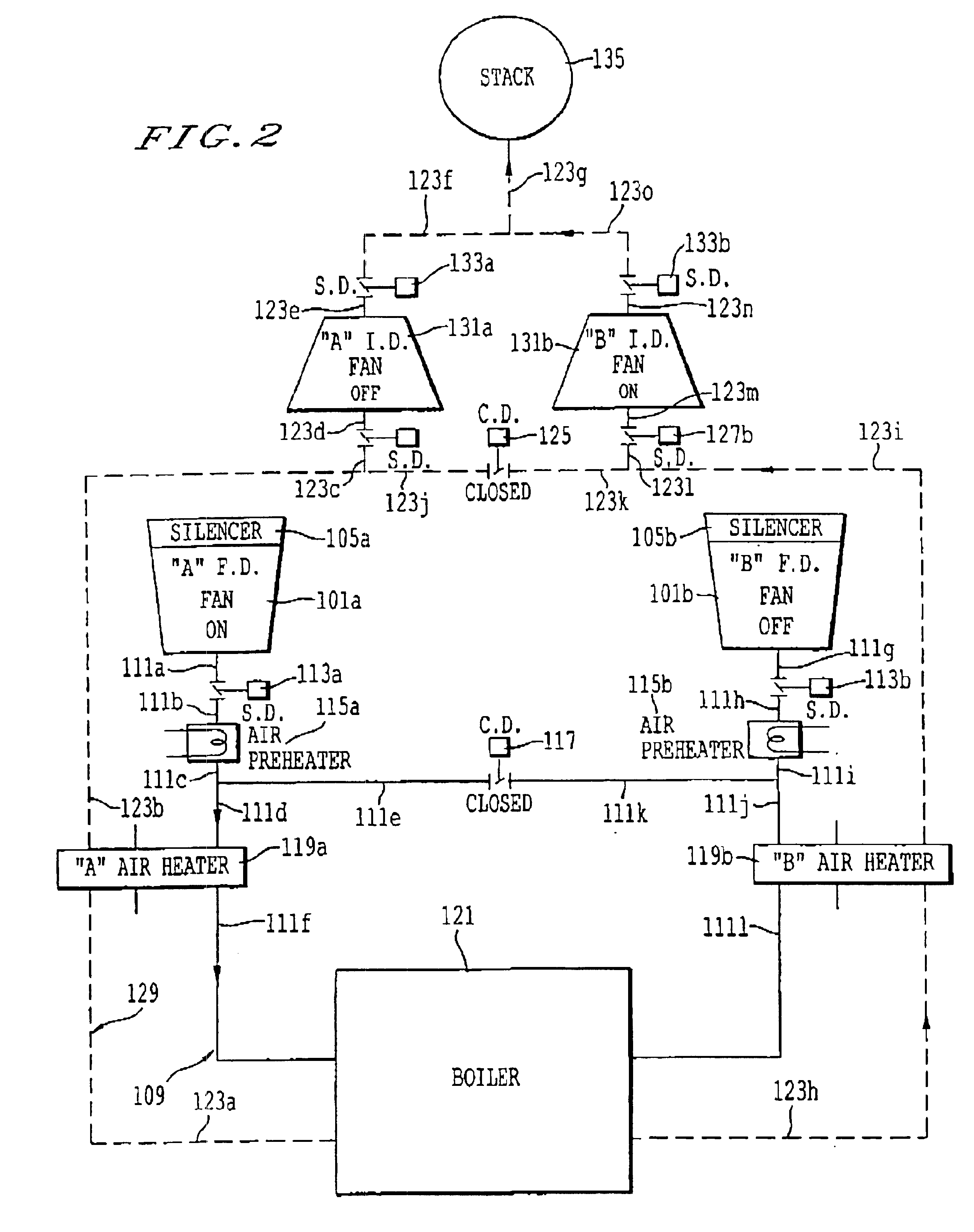
Referring now to the drawings, wherein like reference numerals designate identical or corresponding parts throughout the several views, and more particularly, to FIG. 2 thereof, there is shown a conceptual diagram of an exemplary boiler system of the present invention. According to FIG. 2, the A-side of the boiler system includes forced draft fan 101a, the A air heater 119a, and the induced draft fan 131a. The B-side of the boiler system of FIG. 1 includes forced draft fan 101b, air heater 119b, and induced draft fan 131b.

According to one embodiment, the air heaters 119a and 119b work by passing flue gas on the hot side (the side to the left of the dashed line bisecting air heater 119a and the side to the right of the dashed line bisecting air heater 119b) and bypassing combustion air on the cold side, which is opposite the hot side. The air heaters 119a and 119b are designed to absorb waste heat from the flue gas flowing through the flue gas conduit 129 and transfer this heat to t...


PUM


Abstract

A boiler system includes combustion air conduit for directing the flow of combustion air through a first air heater (e.g., A-side heater) to a boiler and flue gas conduit for directing the flow of flue gas generated by the boiler to a second air heater (e.g., B-side heater). The combustion air conduit is configured to direct the majority of the combustion air to the first air heater, and the flue gas conduit is configured to direct the majority of the flue gas from the boiler to the second air heater.

Description

BACKGROUND OF THE INVENTION1. Field of the InventionThe present invention relates to a system and method for improving the operation of a boiler.2. Description of the BackgroundFIG. 1 shows a conventional boiler system that includes two sets of fans, an “A” set and a “B” set. The A-side set of fans includes forced draft fan 101a, which includes a silencer 105a for reducing noise. The forced draft fan 101a forces combustion air through combustion air conduit 109. Combustion air conduit 109 includes duct sections 111a, 111b, 111c, 111d, 111e, and 111f, which are shown as solid lines with the arrows showing the direction in which combustion air from the forced draft fan 101a is forced. The combustion air conduit 109 also includes shutoff damper 113a, which can be used to reduce or shut off completely the flow of combustion air between duct sections 111a and 111b. Air preheater 115a is located between duct sections 111b and 111c. Air preheater 115a heats combustion air flowing from fan ...

Claims


Application Information

Patent Timeline
IPC IPC(8): F23L15/00F23L5/02F23L15/04F23L5/00
CPCF23L5/02F23L15/04Y10S165/921F23L2900/15043Y02E20/34
Inventor GIELLA, PETER E.
Owner PPL
Why Eureka
Try Eureka