Projection exposure methods and apparatus, and projection optical systems

a technology of projection optical system and projection exposure method, which is applied in the direction of photomechanical apparatus, instruments, printers, etc., can solve the problems of limited material availability, limit to the practical band narrowing, and limited material availability

Inactive Publication Date: 2005-03-08
NIKON CORP
View PDF116 Cites 43 Cited by
  • Summary
  • Abstract
  • Description
  • Claims
  • Application Information

AI Technical Summary

Benefits of technology

With increase in the numerical apertures of the projection optical systems and with increase in the size of the image field, there are increasing demands for minimization of distortion. In order to correct only distortion while suppressing influence on the other aberrations, it is preferable to place an aspheric surface for correction of distortion at a position as close to the object plane (mask) as possible. On this occasion, when the aspheric surface satisfies the foregoing condition (b-1) or (b-2), the distortion can be corrected well even with increase in the numerical aperture and with increase in the size of the image field.

Problems solved by technology

Although the aforementioned excimer lasers, halogen molecular lasers, etc. are available as light sources in the vacuum ultraviolet region of wavelengths not more than 200 nm, there are limits to practical band narrowing thereof.
Since limited materials transmit the emitted light in this vacuum ultraviolet region, available materials are limited for lens elements constituting the projection optical systems and transmittances of the limited materials are not so high, either.

Method used


Image

  • Projection exposure methods and apparatus, and projection optical systems
  • Projection exposure methods and apparatus, and projection optical systems
  • Projection exposure methods and apparatus, and projection optical systems

Examples


first embodiment

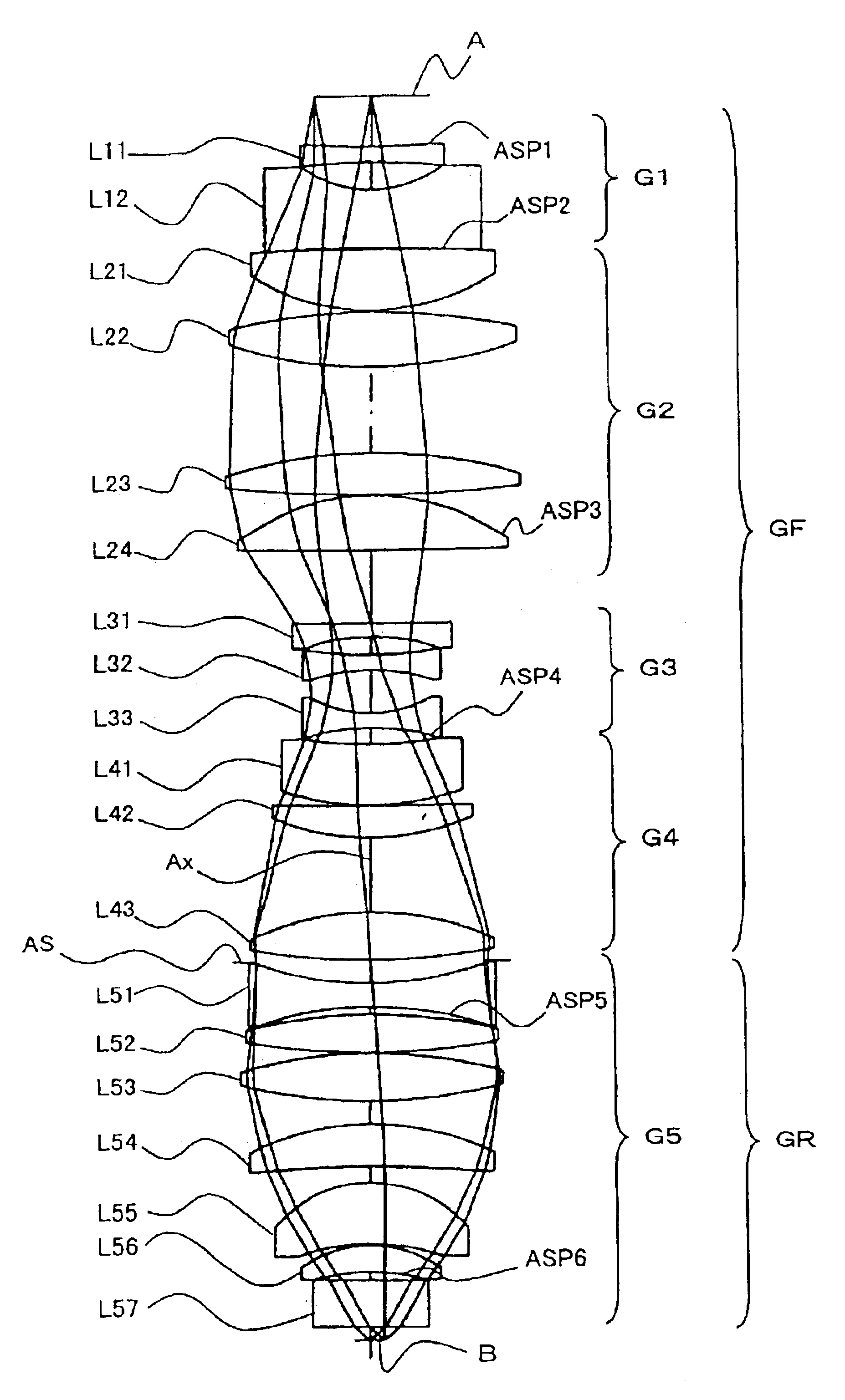
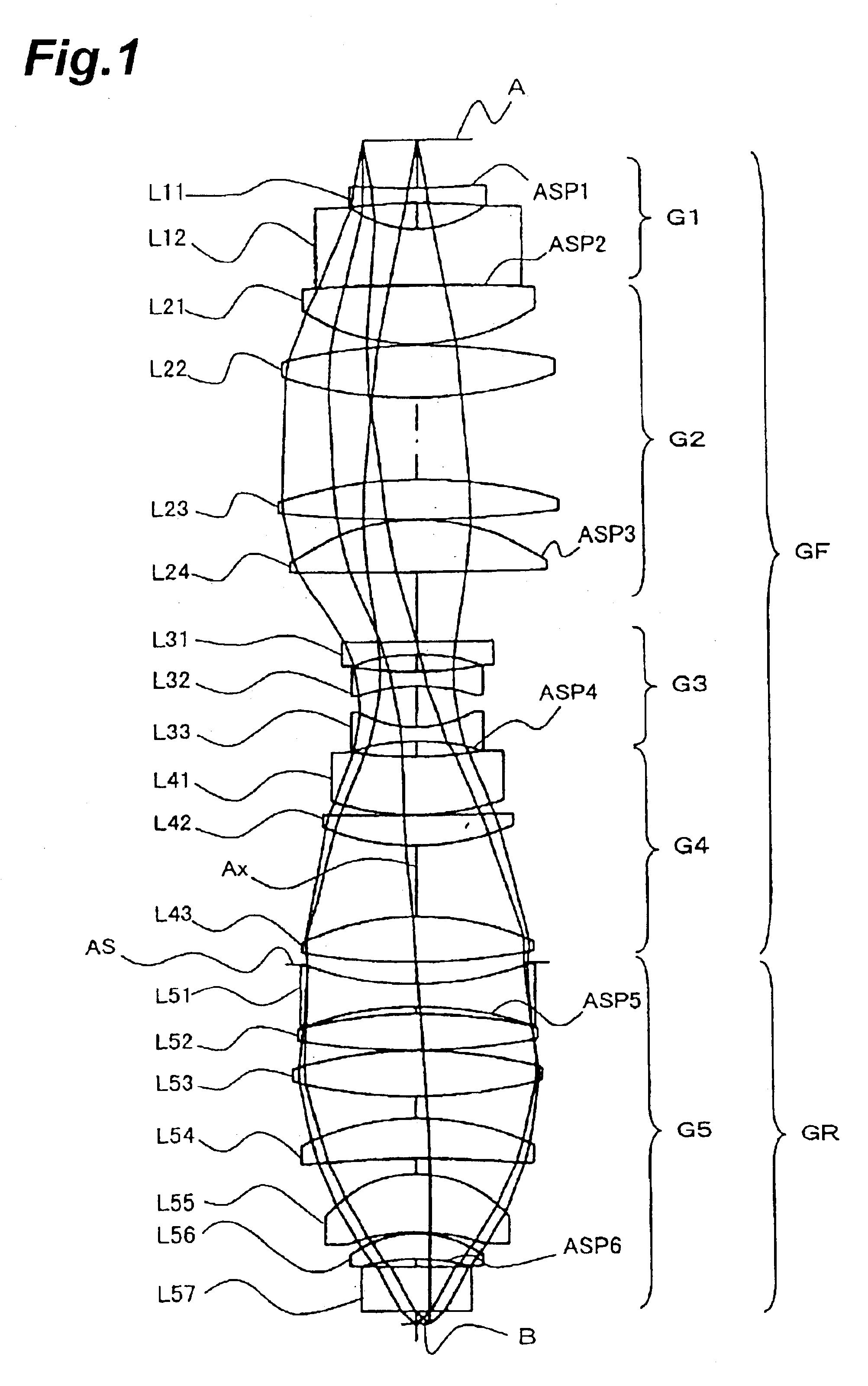
FIG. 1 is the optical path diagram of the projection optical system PL according to the

The projection optical system PL of the first embodiment uses the wavelength of 157.62 nm supplied from the band-narrowed F2 laser, as a reference wavelength and the chromatic aberration is corrected in the range of the wavelength band ±0.2 pm for the reference wavelength. In the first embodiment, all the radiation-transmitting refractors (lenses L11 to L57) in the projection optical system PL are made of fluorite (calcium fluoride, CaF2).

As shown in FIG. 1, the projection optical system PL of the first embodiment has the front lens unit GF of the positive refracting power, the aperture stop AS, and the rear lens unit GR of the positive refracting power in the order named from the first surface A side. According to another grouping, the projection optical system PL of the first embodiment has the negative, first lens unit G1, the positive, second lens unit G2, the negative, third lens unit G3, the...

second embodiment

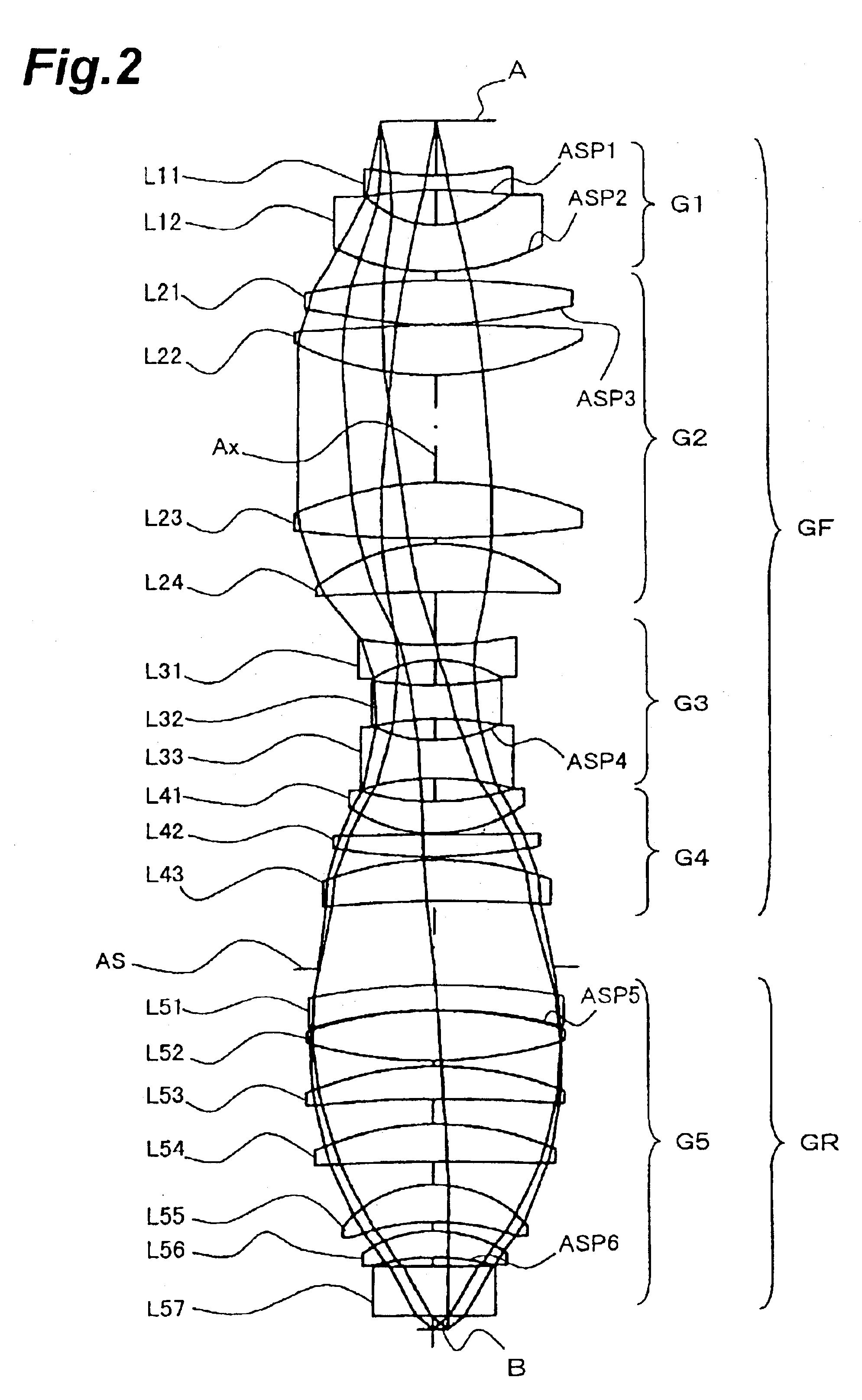
FIG. 2 is the optical path diagram of the projection optical system PL according to the

The projection optical system PL of the second embodiment uses the wavelength of 193.306 nm supplied from the band-narrowed ArF laser, as a reference wavelength and implements correction for chromatic aberration in the range of the wavelength band ±0.4 pm for the reference wavelength. In the second embodiment, the radiation-transmitting refractors in the projection optical system PL are made of silica glass (synthetic quartz) and fluorite.

As shown in FIG. 2, the projection optical system PL of the second embodiment has the front lens unit GF of the positive refracting power, the aperture stop AS, and the rear lens unit GR of the positive refracting power in the order named from the first surface A side. According to another grouping, the projection optical system PL of the first embodiment has the negative, first lens unit G1, the positive, second lens unit G2, the negative, third lens unit G3, th...

fourth embodiment

In the fourth embodiment, as described above, silica glass (synthetic quartz) and fluorite are used as the lens materials (glass materials) and all the lens surfaces of the aspheric shape are formed in the lenses of silica glass.

FIG. 12 is the optical path diagram of the projection optical system according to the fifth embodiment. In this fifth embodiment, silica glass (synthetic quartz) is used as the principal material (second material) of the radiation-transmitting refractors in the projection optical system and fluorite as the achromatizing material (first material).

As shown in FIG. 12, the projection optical system of the fifth embodiment has the front lens unit GF of the positive refracting power, the aperture stop AS, and the rear lens unit GR of the positive refracting power in the order named from the first surface A side. According to another grouping, the projection optical system of the fifth embodiment has the negative, first lens unit G1, the positive, second lens unit...


PUM

PropertyMeasurementUnit
wavelengthaaaaaaaaaa

Abstract

Provided is a dioptric projection optical system favorably applicable to projection exposure apparatus used in the lithography step in fabrication of microdevices such as semiconductor devices. This projection optical system includes a positive, front lens unit (GF), an aperture stop (AS), and a positive, rear lens unit (GR) and is a bitelecentric optical system. The optical system satisfies the following condition:0.065<f2 / L<0.125,where f2 is a focal length of the rear lens unit (GR) and L is a distance between an object and an image.The projection optical system includes at least one aspheric surface (ASP 1 to ASP 6).

Description

TECHNICAL FIELDThe present invention relates to projection exposure apparatus and methods used in fabrication of microdevices, for example, such as semiconductor integrated circuits, imaging devices including CCDs and the like, liquid crystal displays, or thin-film magnetic heads by the lithography technology, and to projection optical systems suitably applicable to such projection exposure apparatus. The present invention also relates to methods of fabricating the foregoing projection exposure apparatus and projection optical systems.BACKGROUND ARTAs the circuit patterns for such microdevices as the semiconductor integrated circuits and others are becoming finer and finer in recent years, the wavelengths of illumination light (radiation) for exposure (exposure light (radiation)) used in the exposure apparatus such as steppers and the like have been decreasing toward shorter wavelengths year after year. Namely, as the exposure light, KrF excimer laser light (wavelength: 248 nm) is g...

Claims


Application Information

Patent Timeline
Patent Type & Authority Patents(United States)
IPC IPC(8): G03F7/20G02B13/14G02B13/18G02B13/22G02B13/24
CPCG02B13/143G02B13/18G02B13/22G03F7/70958G03F7/70241G03F7/70741G03F7/70883G02B13/24H01L21/027
Inventor OMURA, YASUHIRO
Owner NIKON CORP
Why Eureka
Try Eureka