Multi-level monitoring well

a multi-level monitoring and well technology, applied in the field of multi-level monitoring wells, can solve the problems of water contamination, serious environmental and health problems, and seepage into surrounding soils, and achieve the effect of reducing the introduction of aquifer sedimen

a multi-level monitoring and well technology, applied in the field of multi-level monitoring wells, can solve the problems of water contamination, serious environmental and health problems, and seepage into surrounding soils, and achieve the effect of reducing the introduction of aquifer sedimen

US6865933B1Inactive Publication Date: 2005-03-15EINARSON MURRAY D

Image

  • Multi-level monitoring well
  • Multi-level monitoring well
  • Multi-level monitoring well

Examples


Embodiment Construction

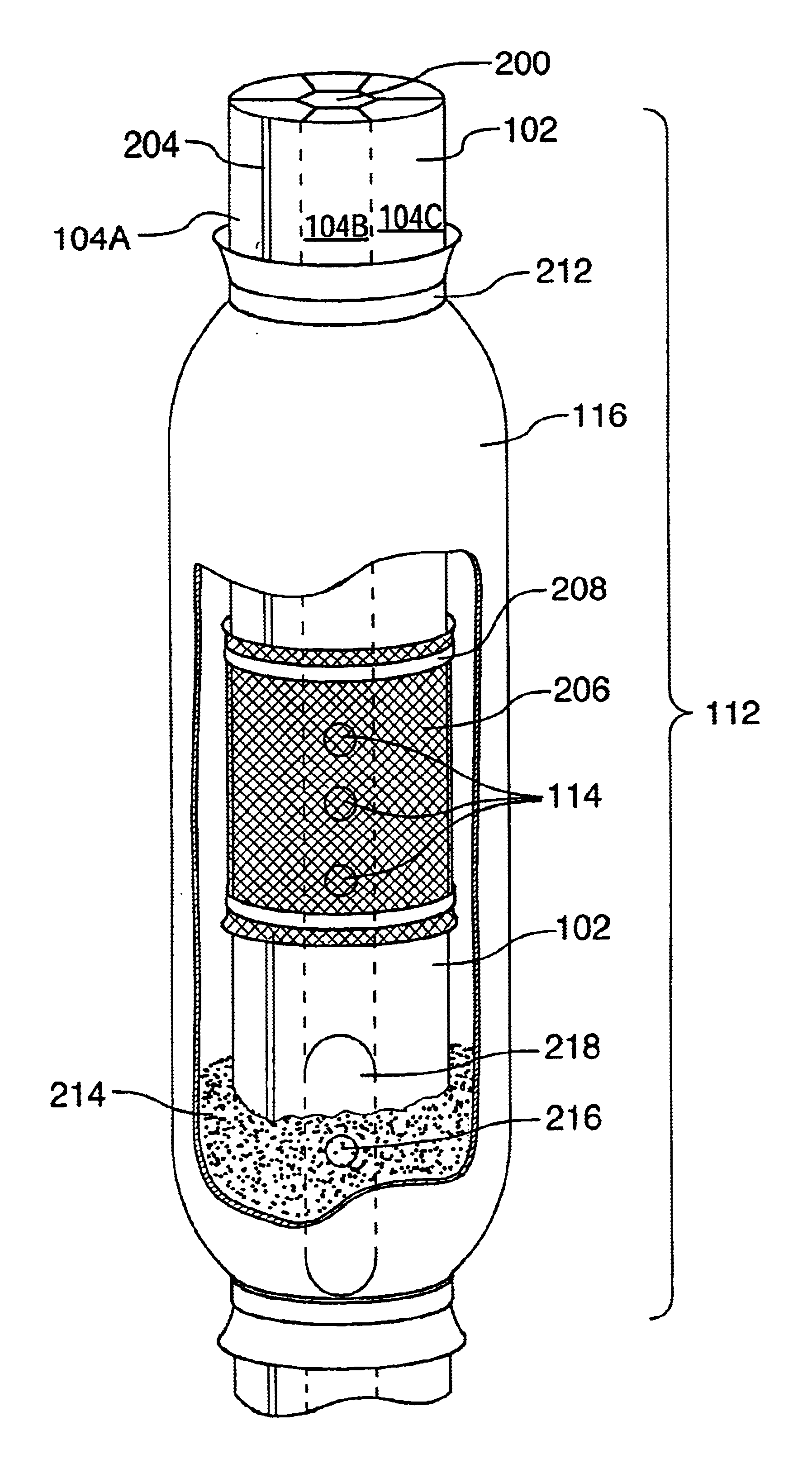
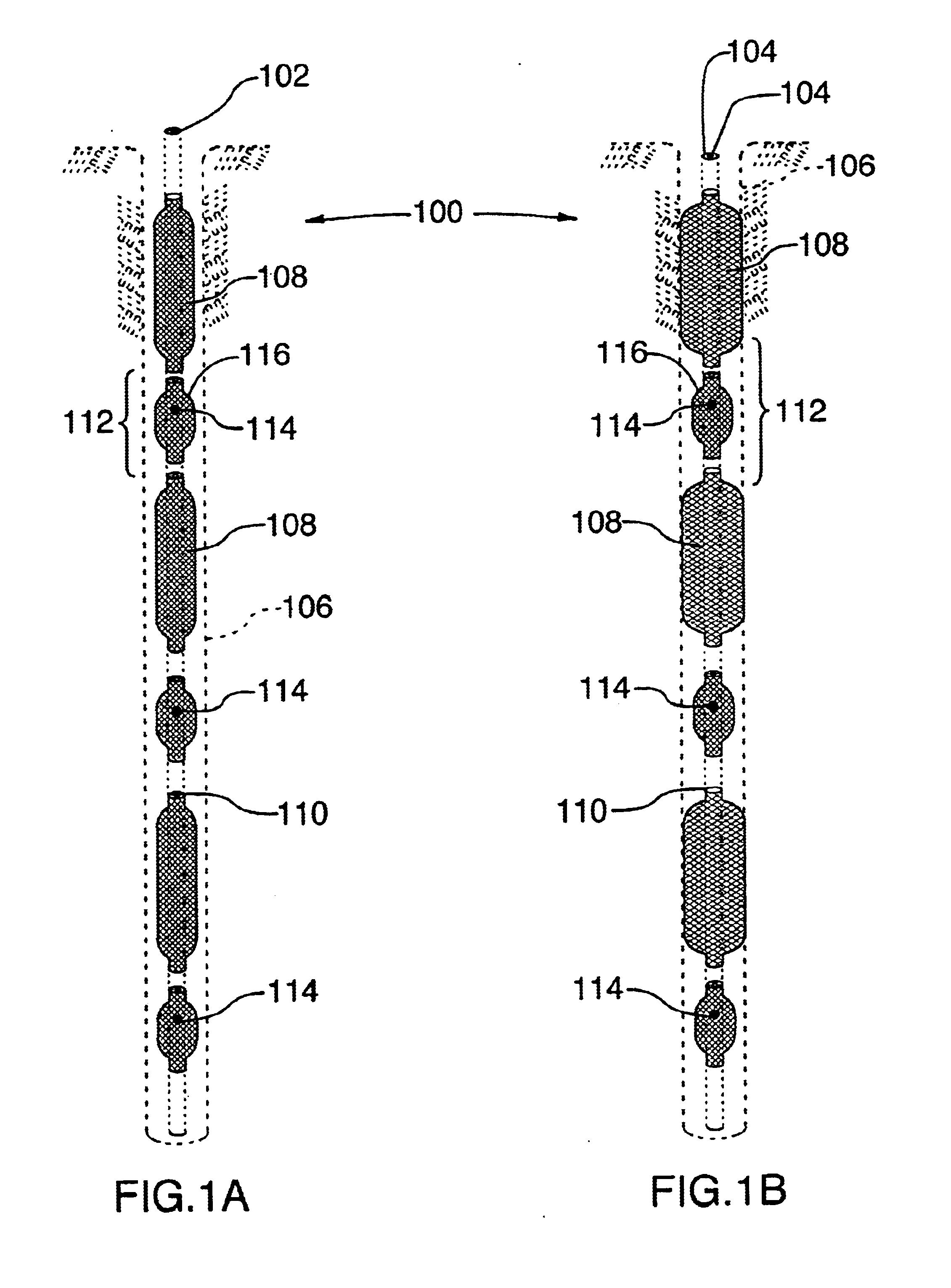
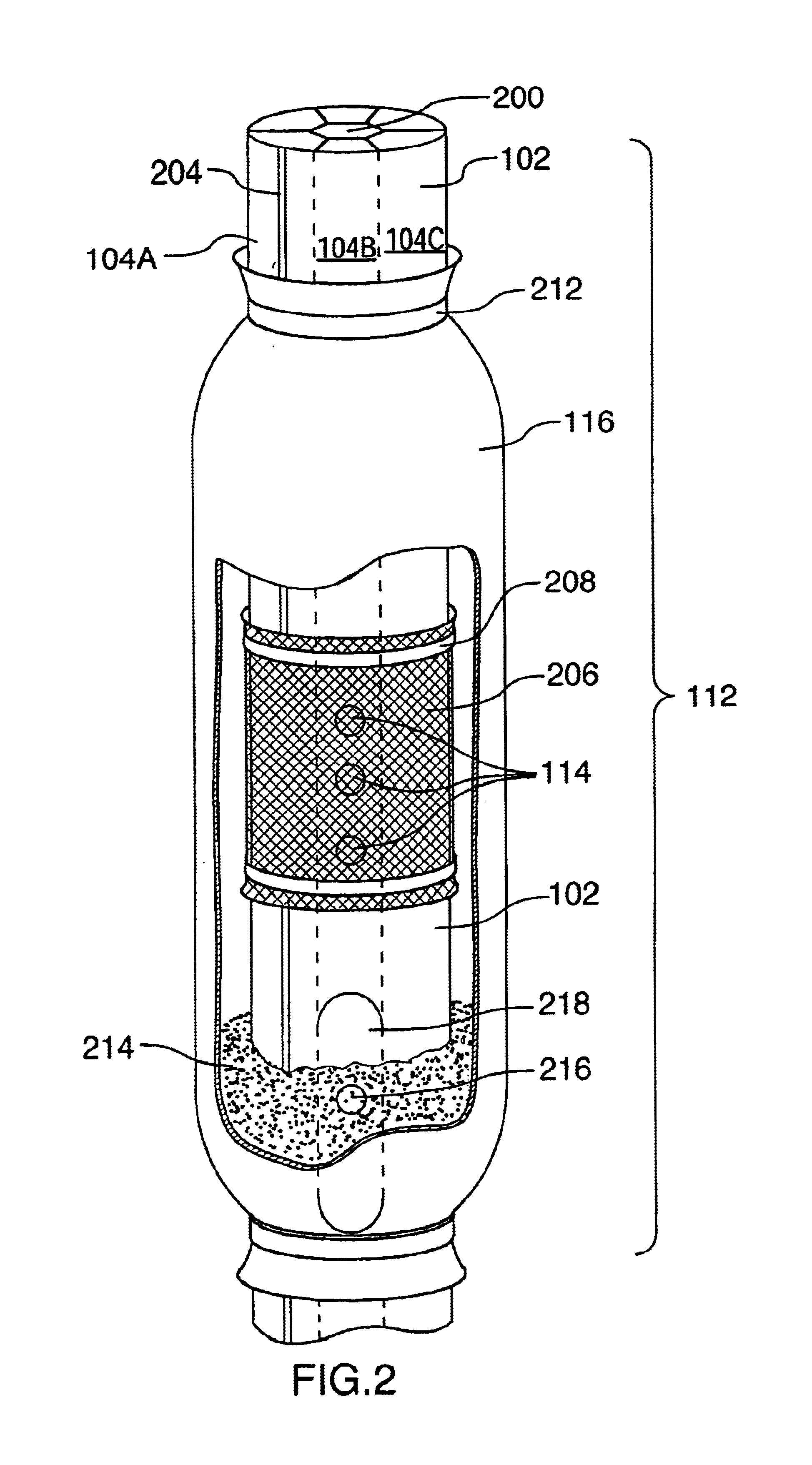
A system 100 includes a central well stock 102, containing two or more internal chambers 104, centered in an exploratory borehole 106, as schematically depicted in FIG. 1. Expandable packers 108 are spaced along the length of well stock 102. The packers are preferably bentonite or another expandable material contained within a permeable, expandable fabric sock (for example, of nylon or geotextile fabric) and surrounding the central well stock 102. Bentonite packers expand upon absorbing water. Accordingly, water can be provided to the packers, which will then expand to seal off different sections of borehole 106 from each other, as seen in FIG. 1B. Isolating sections allows independent samples or measurements to be taken from discrete regions. Packers 108 are preferably attached to well stock 102 by ties 110. Ties 110 can be nylon, plastic or metal, or metal or plastic clamps can be used. Alternative packers, such as a fluid-filled elastic toroid, can also be used.

Packers 108 define...


PUM


Abstract

An apparatus and methods are provided for monitoring a well and for obtaining fluid samples from below the ground. The apparatus includes a single-piece, extruded plastic well stock that extends from the surface of the ground to the lowest sampling depth. Plural sampling intervals are defined between the surface and the lowest sampling depth. Sampling intervals are defined by isolating sections of the borehole by using packers that seal the annular space between the well stock and the borehole. The well stock includes plural longitudinal chambers. Inlet holes are put into the well stock so that inlets for each interval admit fluid to only one longitudinal chamber. Inert sealant is injected below inlets to prevent fluid from spreading below a desired level. Instructions are placed into the longitudinal chambers to monitor fluids in the chambers or to retrieve samples, or alternatively, the well stock can be removed to obtain samples.

Description

BACKGROUND OF THE INVENTIONThe present invention relates to systems for water monitoring and sampling, more particularly, to multi-level monitoring wells. A major objective of the present invention is to provide for enhanced determination of vertical gradients in pressure and water quality in groundwater.Contamination of water is a major environmental concern. Toxic compounds can remain in groundwater, causing serious environmental and health problems, and can seep into surrounding soils. Quick, accurate evaluation of the contamination is critical, especially where there is a threat to health. Because contamination often spreads deep below the surface, and because there are variations in the vertical migration patterns of contaminants, identifying and treating contaminated water and soil can be problematic.The extent and nature of a contaminant spill can be difficult to determine. The rapidity and nature of spread can be unpredictable, depending on the chemical composition and physi...

Claims


Application Information

Patent Timeline
15 Mar 2005
Publication
US6865933B1
IPC
E21B49/08; E21B33/12; E21B33/122; E21B49/00; E21B33/124
CPC
E21B33/122; E21B49/081; E21B33/1243
Inventors
EINARSON, MURRAY D.; CASEY, MICHAEL B.