Thermal condensate reducer for optical devices

a technology of condensate reducer and optical device, which is applied in the direction of material thermal analysis, instruments, mountings, etc., can solve the problems of most detrimental and common forms of particulate contamination, and achieve the effects of reducing thermal distortion, reducing condensation, and being convenient to us

Inactive Publication Date: 2005-03-15
REMOTE SIGHTS
View PDF10 Cites 30 Cited by
  • Summary
  • Abstract
  • Description
  • Claims
  • Application Information

AI Technical Summary

Benefits of technology

The method and system detailed in the disclosed embodiments allow a user to maintain the temperature of optical surfaces to within a tight temperature range of the ambient temperature, or to maintain the temperature of optical surfaces at a set temperature above the dew point, and thus, eliminate the condensation associated with radiative cooling. The disclosed invention is compact, self-contained, portable and adaptable to a wide variety of optical surfaces. The invention has

Problems solved by technology

One of the most detrimental and common forms of particulate contamination

Method used


Image

  • Thermal condensate reducer for optical devices
  • Thermal condensate reducer for optical devices
  • Thermal condensate reducer for optical devices

Examples


Embodiment Construction

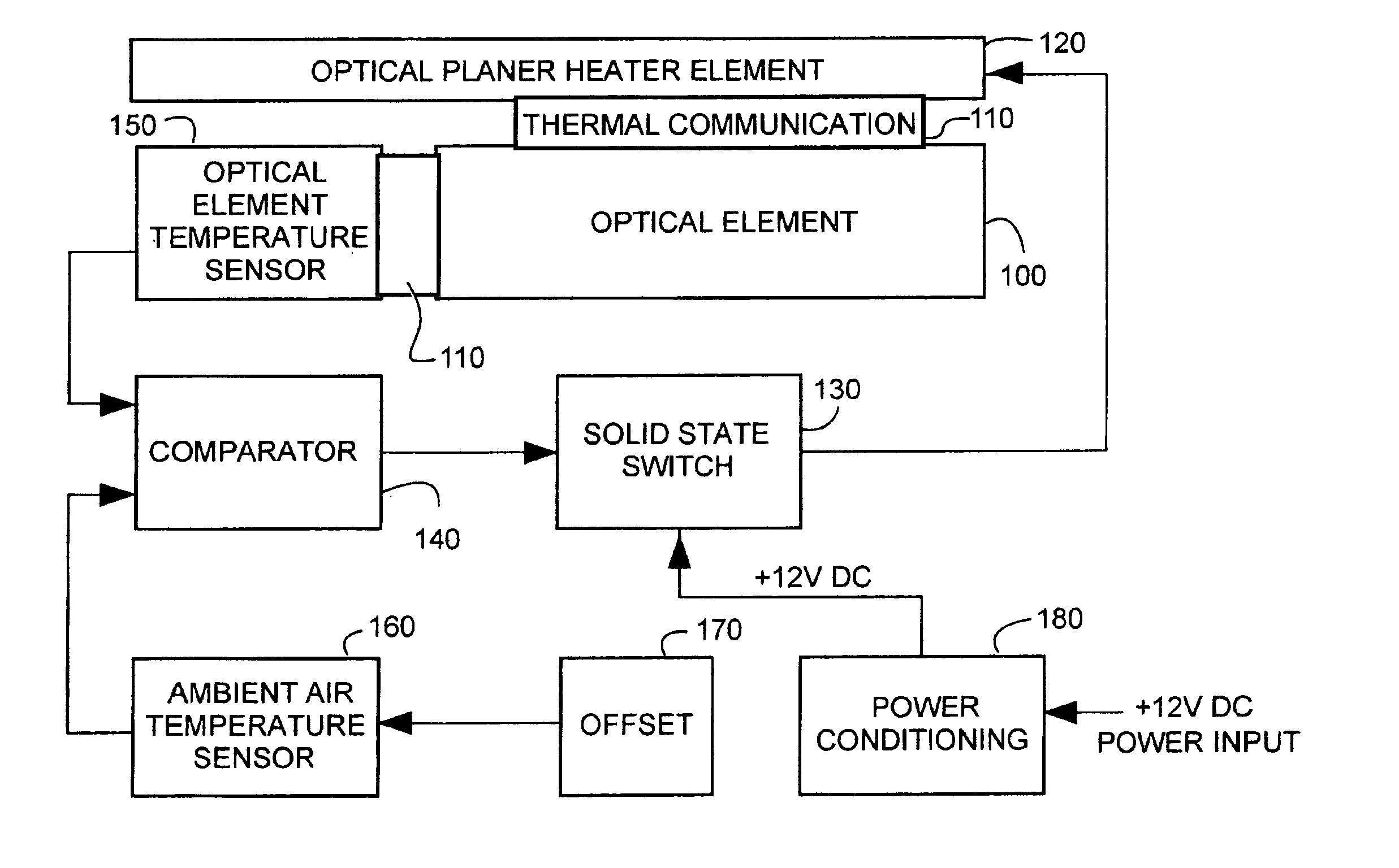
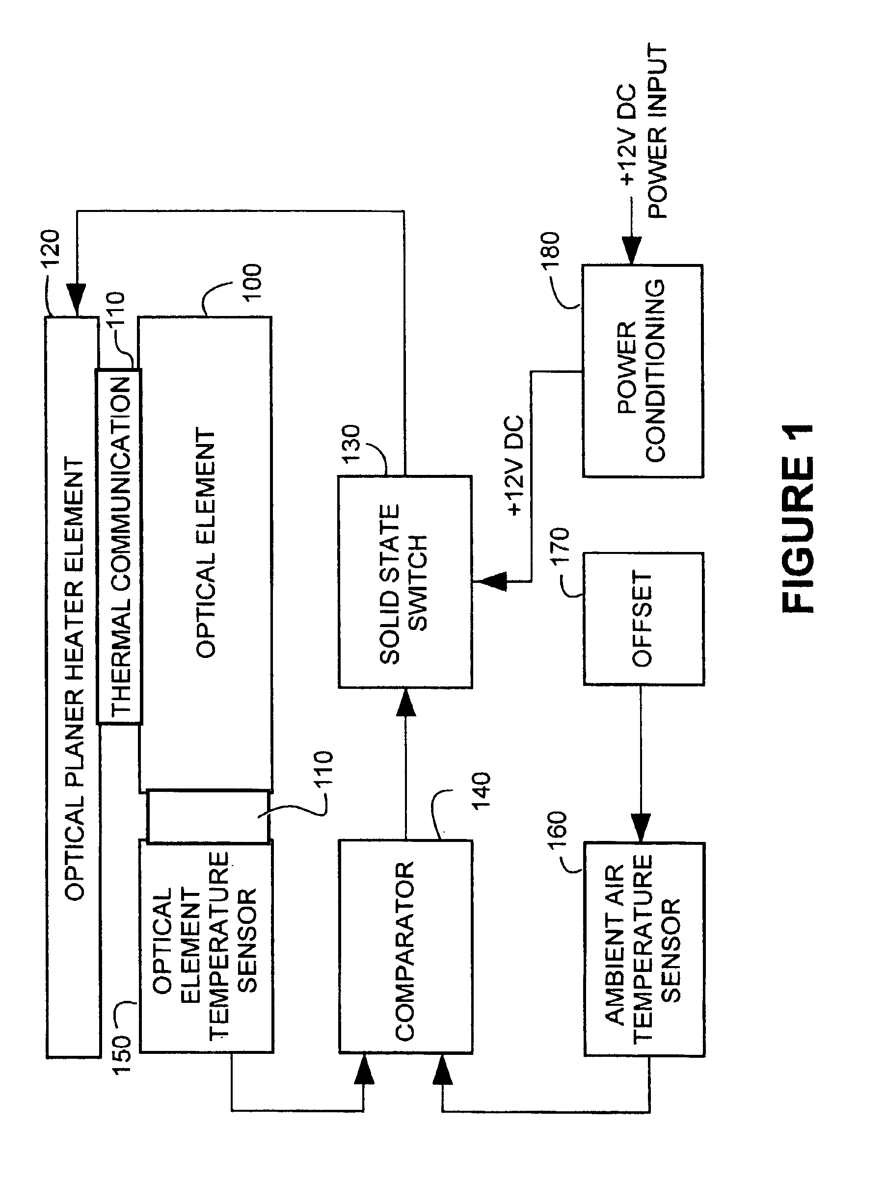
FIG. 1 is a block diagram illustrating the general concepts of at least one embodiment of the present invention. One embodiment disclosed herein has a resistive heater element is in contact with the optical components that are subject to condensation although any manner of transmitting heat can be used including radiative methods such as irradiation. Also in thermal contact with this optical component, is a solid-state precision temperature sensor. In addition, there is a matching solid-state precision temperature in thermal contact with the ambient air, but thermally isolated from the optical element. Signals from these two sensors are applied to a comparator which generates a data signal when the optical temperature sensor is measuring an optical component temperature that is less than the ambient or reference temperature. This data signal is used to activate a solid-state power switch that applies a voltage to a resistive heating element. An offset may also be applied to the refe...


PUM


Abstract

The present invention provides a method and system to overcome and eliminate the effects of condensation contamination of optical surfaces that are induced by radiative cooling. The invention counteracts the effects of radiative cooling on optical surfaces and maintains an optical system within a very tight limit to the ambient temperature by utilizing a resistive heater element that is in contact with the optical components subject to condensation. In thermal contact with this optical component is a solid-state precision temperature sensor. In addition, there is a matching solid-state precision temperature in thermal contact with the ambient air but thermally isolated from the optical element. Signals from these two sensors are applied to a comparator that functions to generate a data signal when the optical surface temperature is less than the ambient or reference temperature. This data signal is used to activate a solid-state power switch that applies a voltage to a resistive heating element. An offset may also be applied to the reference temperature sensor allowing compensation for the thermal resistance of the system comprised of the optical component, optical component attachment heater and temperature sensor.

Description

BACKGROUND OF THE INVENTION1. Field of the InventionThe present invention generally pertains to the reduction and prevention of water vapor condensation on optical systems and particularly to astronomical optical devices used in an outdoor environment.2. Description of the BackgroundOptical devices in general, and astronomical optical devices in particular, are highly sensitive to the effects of particulate contamination degrading the ability of the optical surfaces to refract and transmit light effectively. One of the most detrimental and common forms of particulate contamination is the formation of water condensate on lenses from the surrounding air. This condition can occur in a situation where the relative humidity (RH) of the viewing environment is very high or when the optical components are at a temperature that is less than the surrounding air and particularly if the components are below the dew point of the ambient air.SUMMARY OF THE INVENTIONThe present invention overcomes...

Claims


Application Information

Patent Timeline
IPC IPC(8): G02B27/00G02B7/18G02B7/00
CPCG02B7/008G02B27/0006G02B7/1815
Inventor KRAUSSE, GEORGE J.
Owner REMOTE SIGHTS
Why Eureka
Try Eureka