Automatically measuring the temperature of food

a technology of automatic measurement and temperature, applied in the direction of heat measurement, optical radiation measurement, instruments, etc., can solve the problems of high turnover of personnel, difficult to have an adequate training staff on a permanent basis, and significant additional processing costs incurred by over cooking, so as to minimize overcompensation for temperature, reduce variability between measurements of different workpieces, and save energy.

Inactive Publication Date: 2005-03-15
JOHN BEAN TECH CORP
View PDF26 Cites 41 Cited by
  • Summary
  • Abstract
  • Description
  • Claims
  • Application Information

AI Technical Summary

Benefits of technology

In another embodiment, a plurality of temperature probes are used in a temperature-sensing device to provide the high temperature, the low temperature, and the average temperature. One of the high, low, and average temperature is used in a modeling module to provide for control of the heat engine or conveyor while the actual temperature measurement of the workpiece is in progress. In this manner, the variations between measurements of different workpieces are reduced.
The apparatus according to the invention has numerous advantages. The apparatus automatically measures the temperature of a workpiece. The apparatus helps to ensure that all of the workpieces being processed by a heat engine meet the required minimum or maximum temperatures desired. The apparatus also helps to minimize overcompensating for temperature, thus realizing substantial savings in terms of energy. The apparatus also helps to minimize error introduced by human intervention.

Problems solved by technology

Consequently, significant additional processing costs are incurred by over cooking, which are passed down to the consumer in the form of higher prices.
There is a high turnover of personnel in these plants, making it extremely difficult to have an adequately trained staff on a permanent basis.
This can produce considerable variation in measurements, resulting inevitably in inconsistent results for the various batches of food items being processed.
One cannot be certain that the items that are not measured are, in fact, within the prescribed legal guidelines.

Method used


Image

  • Automatically measuring the temperature of food
  • Automatically measuring the temperature of food
  • Automatically measuring the temperature of food

Examples


embodiment

4. Embodiment

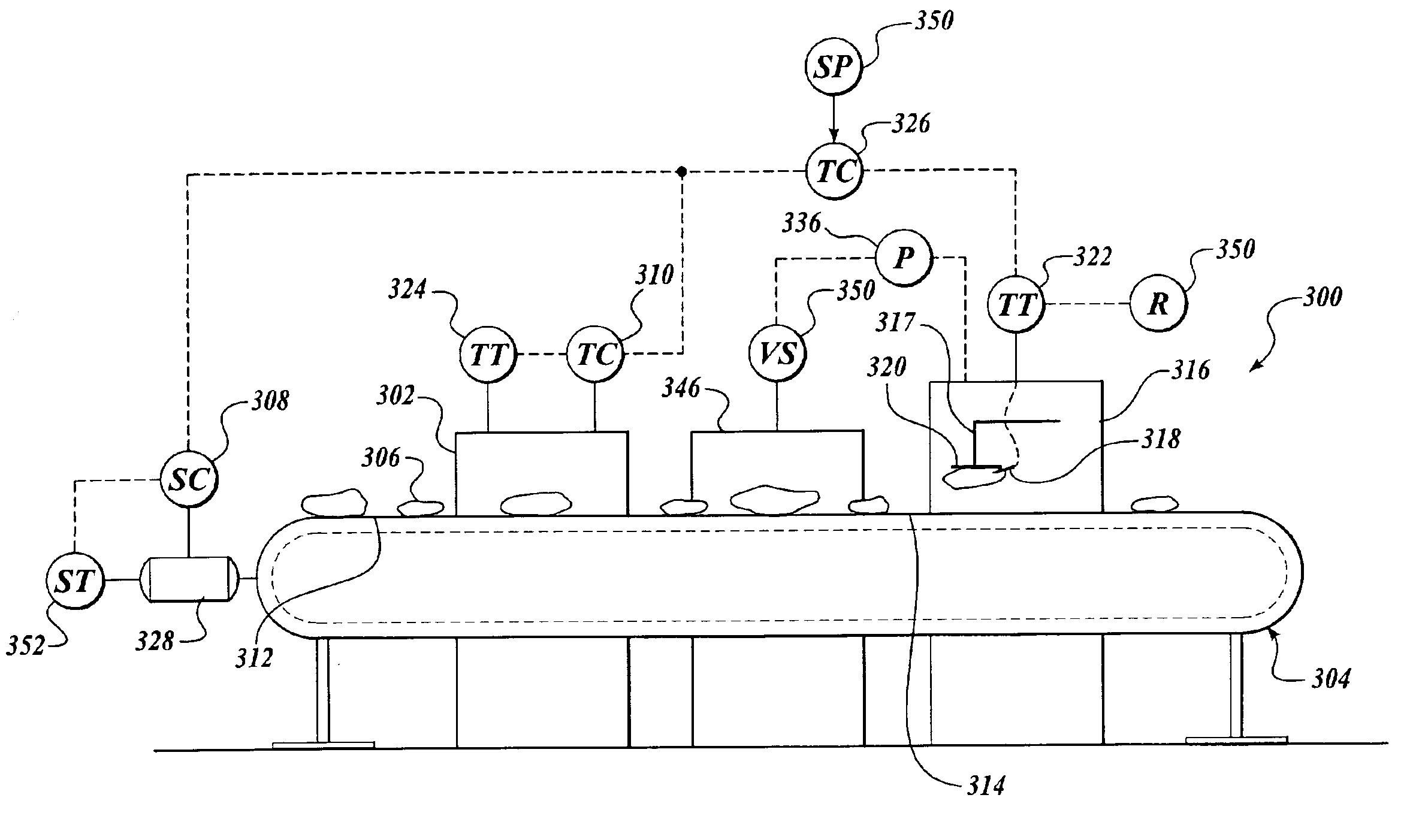
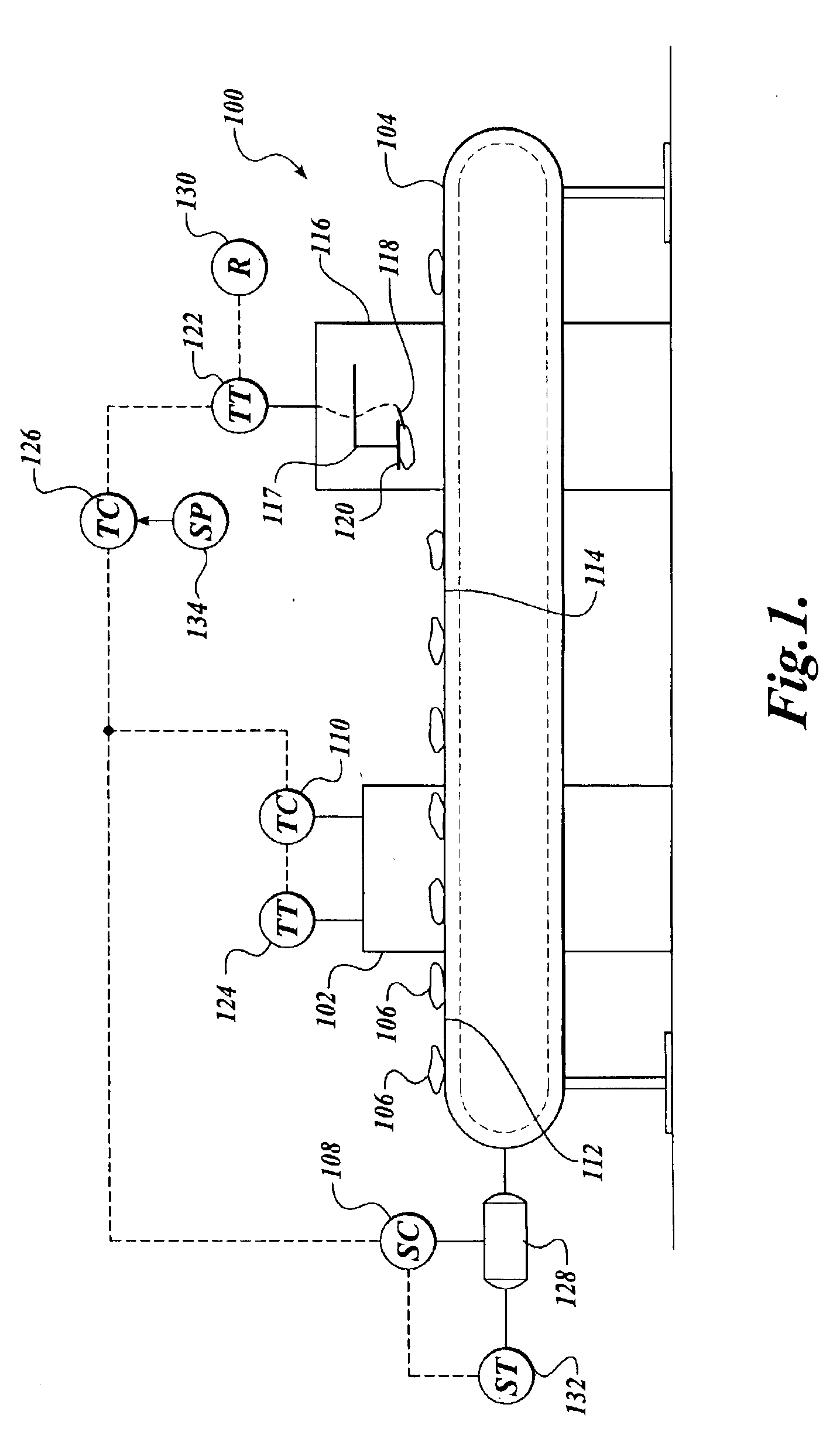
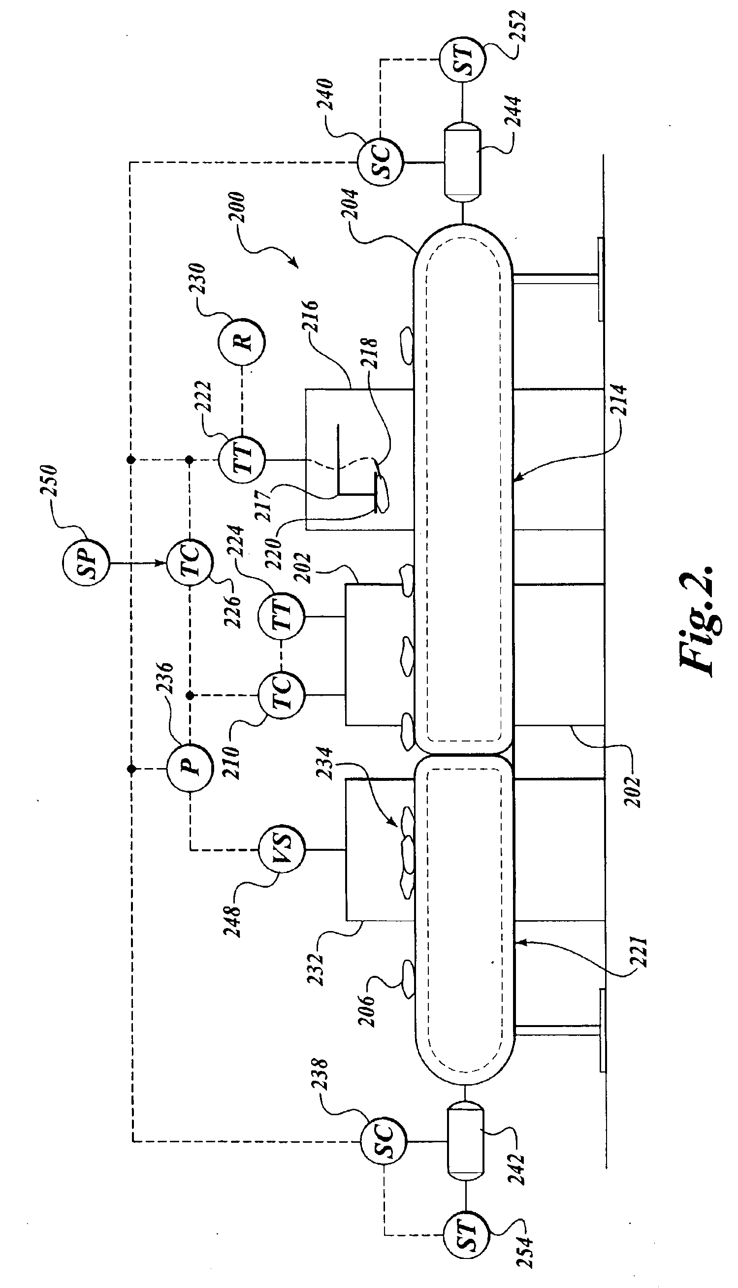
Referring now to FIG. 3, another embodiment of a system 300 used for the automatic temperature measurement of food items is illustrated. The system 300 has components which are similar in some respects to the components of the system 100 of FIG. 1 and the system 200 of FIG. 2. However, in the embodiment illustrated in FIG. 3, a scan system 346 is located downstream of the heat engine 302 and ahead of the temperature measuring station 316. The scan system 346 may include a video camera, a data processor 336, including a memory, in which algorithms may be used to, determine the largest of the workpieces 306 in any given population of workpieces passing on the conveyor 304. Not only can the scan system 346 determine the largest of the food items, it also is capable of tracking the largest workpiece and producing a signal 350 in relation thereto. The output from the processor 336 may be sent to a positioner on the assembly 317 that directs the positioning of the carriage st...


PUM

PropertyMeasurementUnit
temperatureaaaaaaaaaa
temperaturesaaaaaaaaaa
sensing temperatureaaaaaaaaaa

Abstract

An apparatus for measuring the temperature of workpieces transported on a conveyor is disclosed. In one broad aspect of the invention, the apparatus includes a translatable assembly which has a pick-up tool for picking up workpieces and a temperature-sensing device which is in proximity to the pick-up tool for measuring the temperature of the workpiece. Other embodiments are disclosed, including eliminating the pick-up tool, provided the temperature sensing device travels with the workpiece. Scanners can be utilized to designate the largest of the workpieces to be measured or for detecting overlapping workpieces. Feedback temperature control is achieved by varying a parameter, such as conveyor speed or a heat engine temperature. Also, a modeling module can be incorporated to assist with temperature control of the workpieces.

Description

FIELD OF THE INVENTIONThe present invention is directed to a system for measuring the temperature of workpieces traveling on conveyors.BACKGROUND OF THE INVENTIONThe demand for fully cooked meat and poultry items continues to increase with the ever-increasing consumer need for convenience. It is important that food processors deliver food items to the market that are safe to consume. One parameter that significantly ensures that the food items are free of pathogens is to process them to a predetermined temperature. Sometimes the cook temperatures are mandated by regulations. For example, in the United States, the U.S.D.A. prescribes the legal minimum temperatures for the major food categories. Food processors attempt to carry out these prescribed legal guidelines, however, in most situations, the food items are overcooked above the legal minimum temperature to ensure that the delivered food items are safe. Consequently, significant additional processing costs are incurred by over co...

Claims


Application Information

Patent Timeline
Patent Type & Authority Patents(United States)
IPC IPC(8): G01K13/00G01K13/06G05D23/19
CPCG05D23/1935G01K13/06
Inventor GUNAWARDENA, RAMESHWIJTS, CORNEEL CONSTANTARNOLD, JOHN E.RUDY, NORMAN A.
Owner JOHN BEAN TECH CORP
Why Eureka
Try Eureka