System for distribution of electric power

a technology for electric power distribution and system, applied in the direction of transformer/inductance casing, transformer/inductance cooling, cable installation apparatus, etc., can solve the problems of transformer damage and pollution, reduce the number of control/monitoring interfaces, reduce the number of separate units, and reduce the number of electric connections

Inactive Publication Date: 2005-03-15
VETCO GRAY SCANDINAVIA
View PDF8 Cites 45 Cited by
  • Summary
  • Abstract
  • Description
  • Claims
  • Application Information

AI Technical Summary

Benefits of technology

Another advantage of the present invention is that the second chamber will serve as an additional barrier for the transformer. This additional barrier will eliminate the need for a double tank design of the transformer housing.
is that the second chamber will serve as an additional barrier for the transformer. This additional barrier will eliminate the need for a double tank design of the transformer housing.
The integration of the distribution unit and the transformer into one single module will also reduce the number of control / monitoring interfaces. This integration will also imply that a reduced number of separate units have to be installed subsea and that a reduced number of electric connections have to be made up subsea.

Problems solved by technology

Water leaking into the transformer chamber can cause electric shorts between the windings, which damages the transformer.
To maintain this barrier intact is a problem for the manufacturer as the unit experiences a great span of pressures from the surface down to the sea bottom.
An eventual leak will also pose a pollution problem.

Method used


Image

  • System for distribution of electric power
  • System for distribution of electric power
  • System for distribution of electric power

Examples


Embodiment Construction

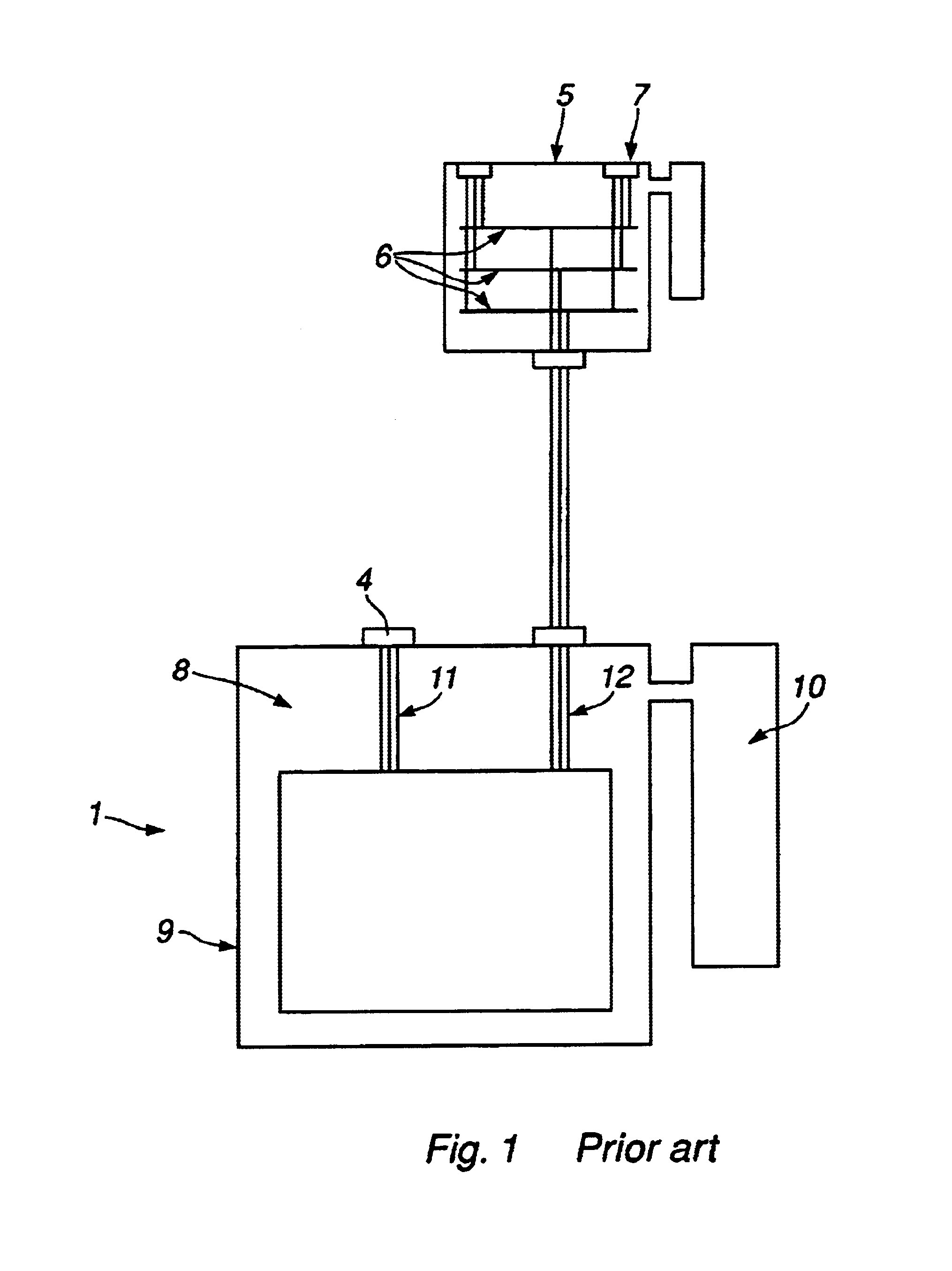
FIG. 1 gives an overview of a subsea power distribution system according to prior art. In said system the transformer 1 is the electrical link between a high voltage transmission system and a local distribution system. The transmission voltage, typically 11 kV-36 kV, is transformed down to a distribution level, typically 3.0 kV-12.0 kV. The traditional design of a transformer is to have a single three-phase primary connection 11 and a single three-phase secondary connection 12. The primary input is connected to the transmission line via a high voltage connector 4 mounted on the top of the transformer housing 9.

The secondary output 12 from the transformer is connected to a separate distribution or switchboard unit 5. The distribution components in said unit include a busbar arrangement with connectors and switches connecting the transformer to the consumer equipment. There is one busbar 6 per phase. The consumers are connected to the busbars 6 via connectors 7 mounted on the wall of ...


PUM

PropertyMeasurementUnit
electric poweraaaaaaaaaa
pressureaaaaaaaaaa
flexibleaaaaaaaaaa

Abstract

A subsea electrical power distribution system including a first chamber (20) housing a transformer, a second chamber (30) housing a power distribution system with busbars (32) for distribution of power to individual consumers connected to said busbars via connectors (33). The interface between the first and second chamber includes a flexible membrane (22) allowing the oil in the first chamber to expand into the second chamber and vice versa. The second chamber being connected to an external volume expansion chamber (34) allowing the pressure in the second chamber to balance against the pressure of the ambient sea.

Description

FIELD OF THE INVENTIONThe present invention relates to a system for distribution of electric power between a transmission system and local consumers, especially in a subsea environment.TECHNICAL BACKGROUNDIn said system the transformer is the electrical link between the high voltage transmission system and the local distribution system. The output from the transformer is connected to a separate distribution or switchboard unit connecting the transformer to the user equipment.Transformers for subsea installations customary consist of a chamber housing the transformer proper with core and copper windings. This chamber is filled with transformer oil. To balance the internal pressure of the chamber to the ambient seawater pressure, the transformer assembly is equipped with a volume compensator in the form of an external expansion chamber.This compensator constitutes a barrier against the surrounding water that is important for the correct operation of the transformer. Water leaking into...

Claims


Application Information

Patent Timeline
Patent Type & Authority Patents(United States)
IPC IPC(8): H01F27/10H01F27/14H01F27/02
CPCE21B33/0385H01F27/14H01F27/02H05K5/068
Inventor HAFSKJOLD, GUNNARS.O SLASHED.LVIK, NILS-ARNE
Owner VETCO GRAY SCANDINAVIA
Why Eureka
Try Eureka