Continuous mode voltage fed inverter

a voltage-feeding inverter and continuous-mode technology, which is applied in the direction of instruments, basic electric elements, light sources, etc., can solve the problems of lamp reaches the end of its useful life, undesirable flicker, and unsatisfactory discontinuity of output voltag

Inactive Publication Date: 2005-03-15
GENERAL ELECTRIC CO
View PDF15 Cites 22 Cited by
  • Summary
  • Abstract
  • Description
  • Claims
  • Application Information

AI Technical Summary

Problems solved by technology

The use of the pulse shutdown technique will, however, cause an undesirable discontinuity of the output ...

Method used


Image

  • Continuous mode voltage fed inverter
  • Continuous mode voltage fed inverter
  • Continuous mode voltage fed inverter

Examples


Embodiment Construction

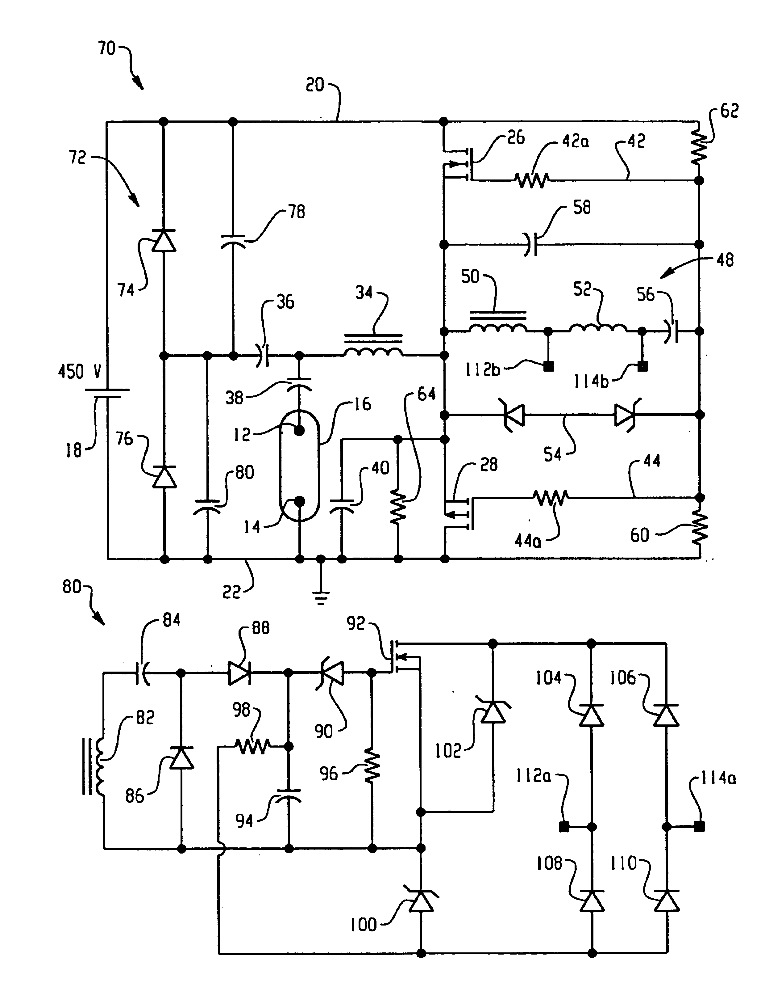
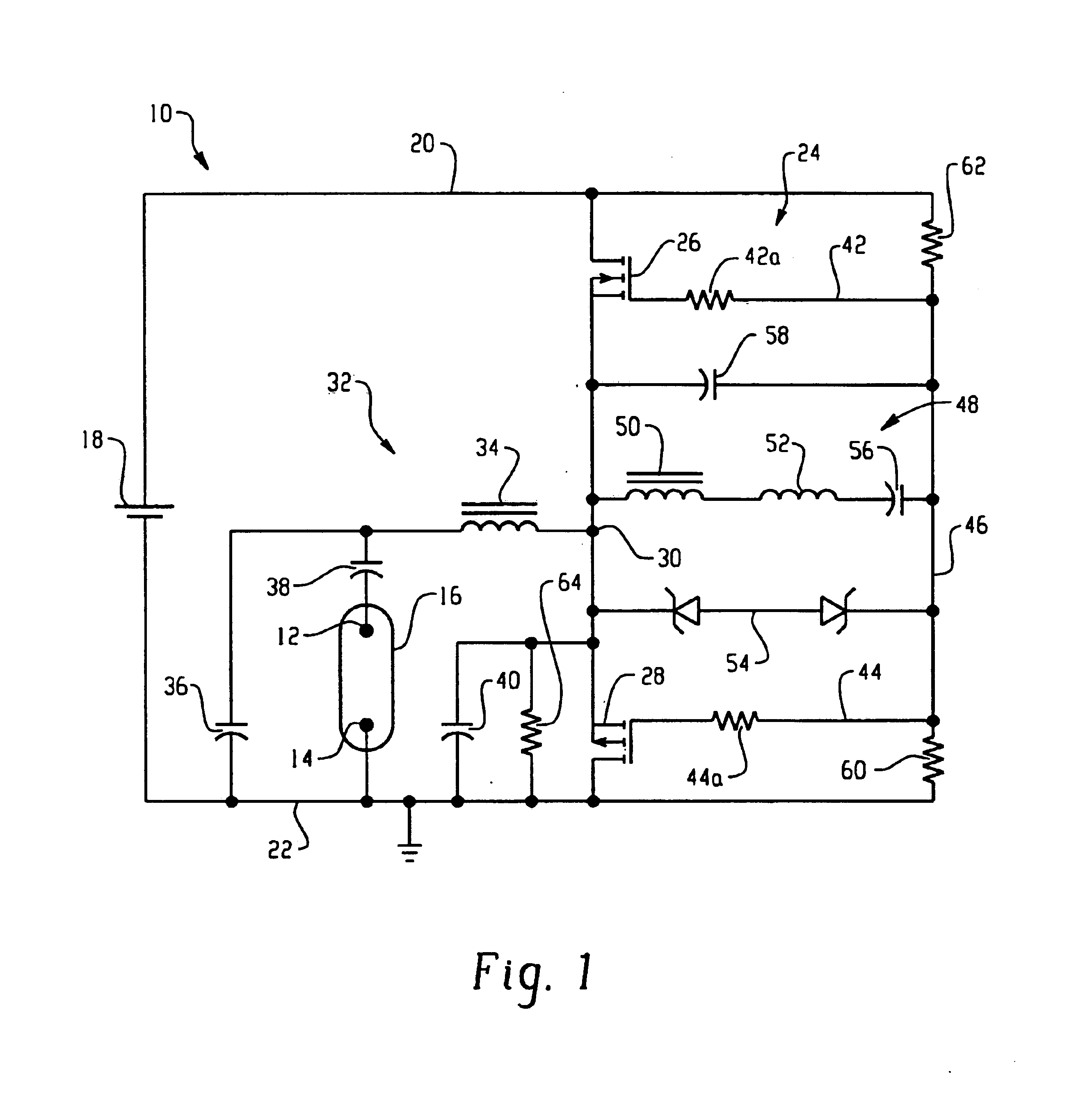
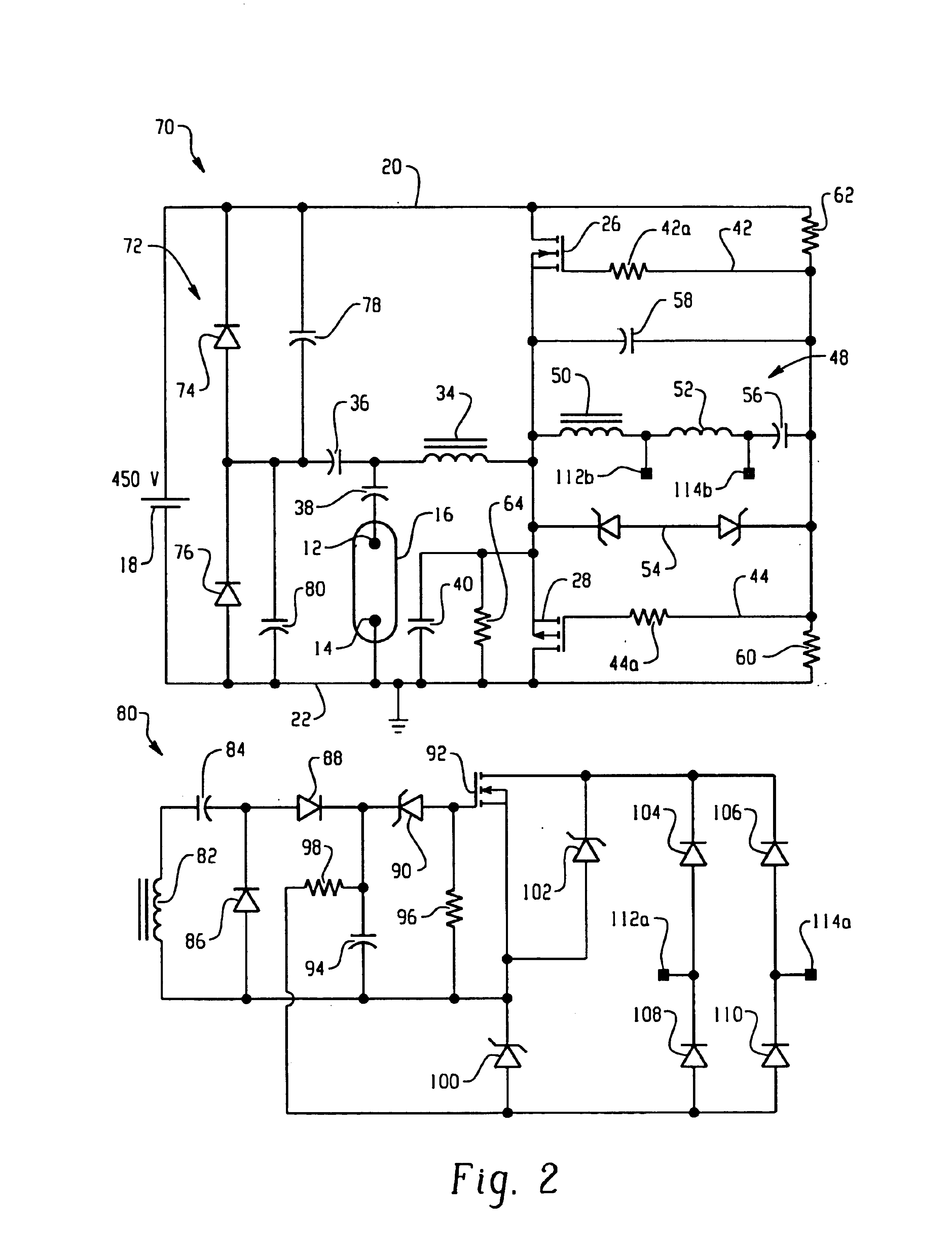
FIG. 1 shows an inverter circuit 10 which may be altered in accordance with the concepts of the present application. The configuration of the circuit prior to the alteration, includes a pair of lamp connectors 12 and 14 configured to hold a lamp 16, such as a gas discharge lamp. Lamp 16 is powered from a d.c. bus voltage generated by source 18. The d.c. bus voltage exists between a bus conductor 20 and a reference conductor 22, and such voltage is converted to a.c., by d.c.-to-a.c. converter 24.

Switches 26 and 28, serially connected between conductors 20 and 22, are used in the conversion process. When the switches comprise n-channel and p-channel enhancement mode MOSFETs, respectively, the source electrodes of the switches are connected substantially directly together at a common node 30. The switches may comprise other devices having complementary conduction modes such as, but not limited to, pnp and npn Bipolar Junction Transistors. A resonant load circuit 32 includes a resonant ...


PUM


Abstract

In accordance with one aspect of the present application, a continuous mode voltage fed inverter includes a resistor starting network configured to start a charging of the inverter. A resonant feedback circuit is configured to generate an oscillating signal following the starting of operation of the circuit by the resistor starting network. A complementary switching network has a pair of complementary common source connected switches configured to receive the oscillation signal generated by the resonant feedback circuit, wherein the oscillation signal determines a switching rate of the complementary pair of switches. A clamping circuit is configured to maintain an inverter current in an inductive mode, wherein the inductive current lags voltage across the pair of complementary common source connected switches. A fold-back circuit is connected, in one embodiment, to the complementary switching network to provide a two-level clamping action. A first-level clamps the output voltage sufficient to permit a starting of the lamp. A second level of the two-level clamping arrangement of the fold-back circuit clamps the output voltage to protect the inverter from overheating when a lamp is removed from the circuit.

Description

BACKGROUND OF THE INVENTIONThe present application is directed to resonant inverter circuits, and more particularly to a voltage fed resonant inverter which operates continuously, from an open circuit condition at the output terminals to a short circuit condition.Existing inverters include open- or short-circuit protection circuitry. One particular type of protection is through the use of pulse shutdown operations. In these designs, either the output voltage and / or the current that flows through resonant components or semiconductor switches is sensed to assist in the shutdown. When an open circuit situation occurs, such as when a lamp reaches its end-of-life, the maximum inverter current is detected, and the inverter is disabled or shut down before the components are overstressed. The use of the pulse shutdown technique will, however, cause an undesirable discontinuity of the output voltage. To accommodate new lamps which may not have recycling power, the inverter may also be period...

Claims


Application Information

Patent Timeline
IPC IPC(8): H05B41/285H05B41/28
CPCH05B41/2855Y10S315/04
Inventor NERONE, LOUIS R.MIESKOSKI, JAMES D.
Owner GENERAL ELECTRIC CO
Why Eureka
Try Eureka