
3D cursor or joystick device

a joystick and cursor technology, applied in static indicating devices, instruments, teaching apparatuses, etc., can solve the problems of insufficient current peripheral input devices, cumbersome and burdensome users, no logical correlation between pressing a key or button, etc., and achieve the effect of low cost and simple manufacturing

Inactive Publication Date: 2008-07-29
MAUI INNOVATIVE PERIPHERALS
View PDF14 Cites 19 Cited by
  • Summary
  • Abstract
  • Description
  • Claims
  • Application Information

AI Technical Summary

Benefits of technology

[0009]Accordingly, it is a principal object of the present invention to provide a system for 3D navigation by a user on linear and rotational axes on a display that is reliable, simple to manufacture, and low in cost. It is a particular object of the invention that the 3D navigation system can be operated by a simple unit worn on the user's head in order to leave the user's hands free for simultaneous input in interactive games or manipulation of other controls.
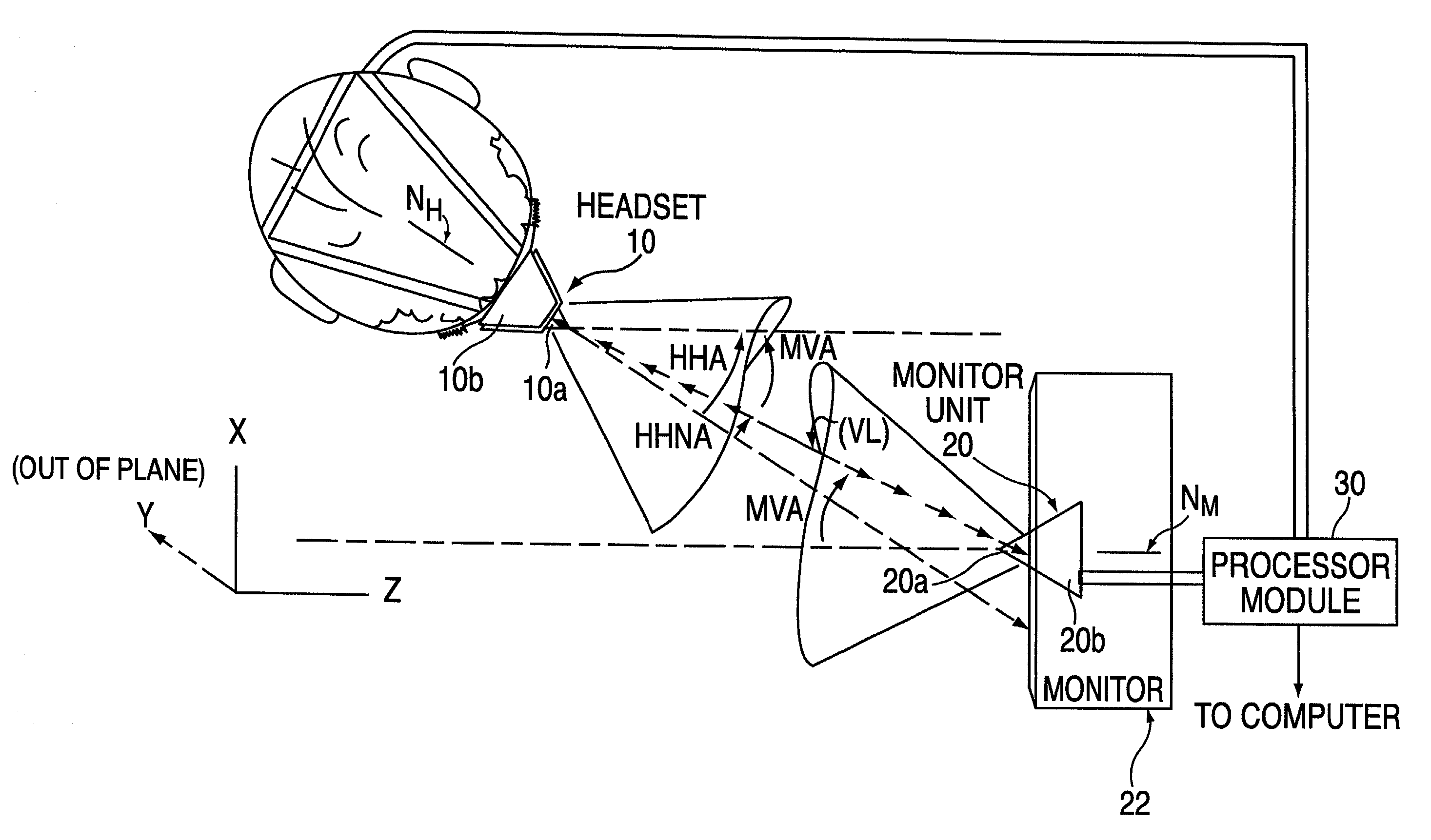
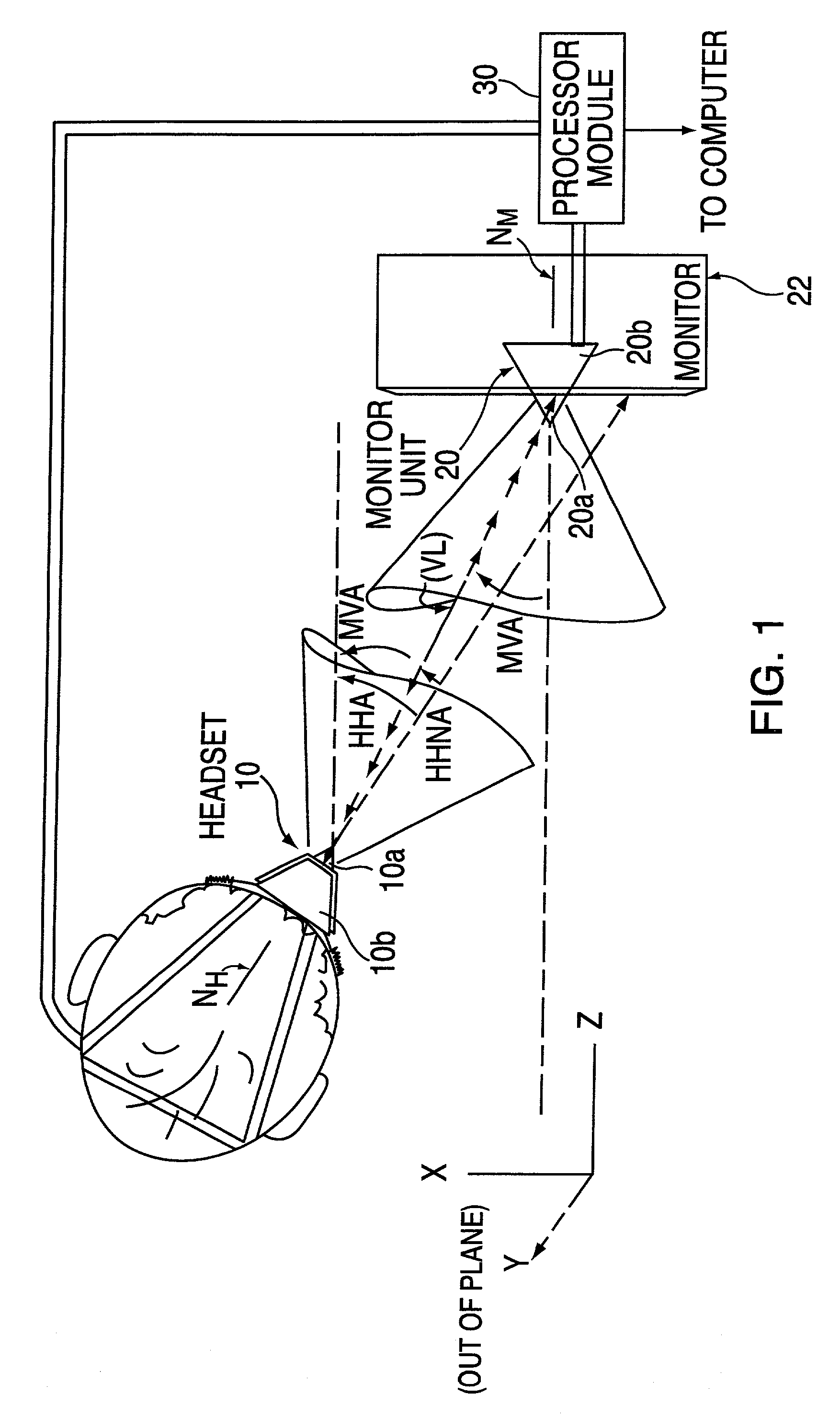
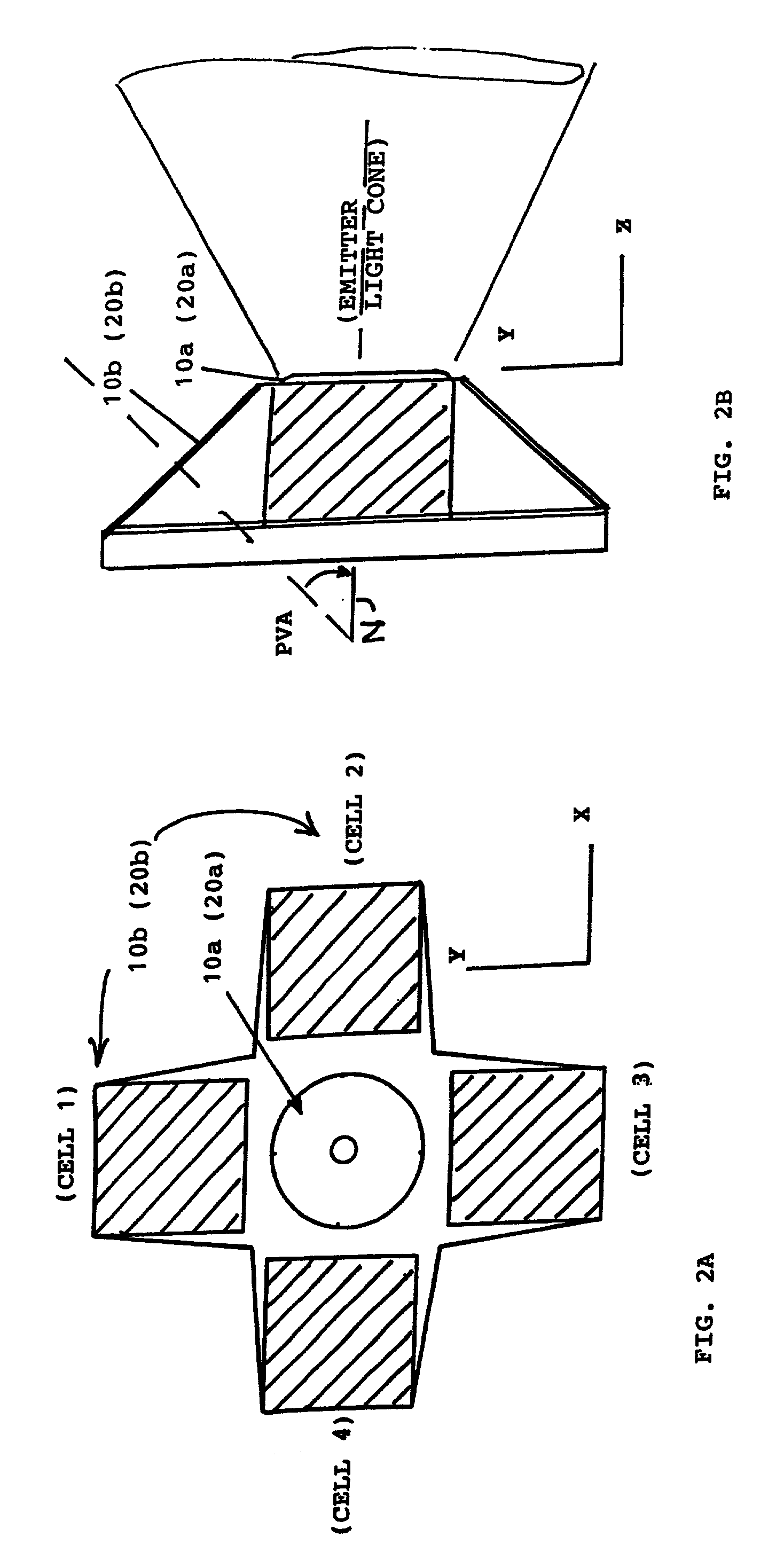
[0012]The photodetector cells are preferably 4 silicon photovoltaic (PV) cells or photodiodes spaced symmetrically around a central infrared emitter element, and angled outwardly at 30 to 45 degrees to the central axis of the unit. The detector surfaces of the PV cells or photodiodes perferably have filter elements superimposed on them to filter out ambient background light from the infrared light beam. The infrared emitter element preferably has a peak spectral output in the 900 nanometer (nm) range corresponding to the peak sensitivity range of the PV cells. Both the user-worn and stationary emitter / detector units have an identical construction and components in order to lower the cost of manufacture in quantity.
[0014]The 3D navigation system of the invention can also be used for hands-free control in a wide range of other applications and environments besides games. It may be used to control flight motions and display views in a simulator or cockpit of an aircraft, or the command center of a naval vessel, spaceship, land vehicle, etc. Leaving the user's hands free allows for simultaneous control of other functions, such as manipulation of controls on a control panel or the firing of weapons. For disabled persons, the hands-free 3D navigation system can be used to control input to a computer, the movements of a motorized wheelchair, prosthetic device, and other assistance devices for the disabled. The 3D navigation system may also be used to control various functions in an industrial environment, for example, guiding the machine-assisted movement and orientation of a workpiece while leaving the operator's hands free to manipulate process equipment applied to the workpiece (welding, painting, laminating, etc.). The system can similarly be used in CAD design, architectural, medical graphics, virtual reality, and other commercial applications. For example, use of the headset with a virtual reality display can allow a 3D “tour” to be taken through construction sites, buildings, medical diagnostic images, and simulated or artificial environments.

Problems solved by technology

The current peripheral input devices are inadequate for several reasons.
This is cumbersome and burdensome for the user.
Secondly, there is no logical correlation between pressing a key or button and directing movement, camera angle, or pointing on a display.
Such “one-way” transmitter / receiver detection systems have the limitation that they can be used to compute the head unit's position or its orientation, but not both at the same time with accurate results.
Computational tradeoffs are made to obtain primarily position information or orientation information, but cannot obtain accurate information in “six degrees” of freedom, i.e., on linear axes (X, Y, Z) and rotational axes (yaw, pitch, roll) at the same time.
More complex systems have been devised for accurate 6-degrees-of-freedom (so-called 6DoF) calculations, but these have required expensive and complex equipment for optical scanning of a three-dimensional target array worn or held by the user from multiple camera angles, e.g., as described in U.S. Pat. Nos. 5,889,505 to Toyama, 5,884,239 to Romanik, 5,461,478 to Sakakibara, 5,227,985 to DeMentheon, 5,187,540 to Morrison, and 4,649,504 to Krouglicof et al.

Method used


Image

  • 3D cursor or joystick device
  • 3D cursor or joystick device
  • 3D cursor or joystick device

Examples


Embodiment Construction

[0022]A fundamental principle of the present invention is the use of complementary (two-way) position / angle detection to provide a sufficient set of determinative variables from which the coordinate position along linear axes and angular orientation along rotational axes of a movable unit can be determined relative to a stationary one. The movable unit is placed or worn a movable part of the user's body so that its movements can be used in a lifelike or natural manner for 3D navigation control of a cursor, instrument, character, etc., on a display of an associated computer running the corresponding 3D application program. In the following detailed description, a preferred embodiment of the invention is described in which identical infrared-emitter and photovoltaic-cell-array detector units are worn on the user's head and mounted on top of a display monitor. However, it is to be understood that many other variations may be used and still be encompassed within the guiding principles o...


PUM


Abstract

A 3D cursor or joystick device and control method employs a complementary pair of emitter / detector units, one worn on a part of a user's body (e.g., the head) and the other mounted in a stationary position on a display monitor facing the user. Each unit has an array of photovoltaic (PV) cells centered on a normal axis and an infrared diode for emitting a light beam on the normal axis. Each photodetectors array receives the infrared beam from the other unit and provides output signals representing the light intensities of the received beam on the PV cells. The PV cell response signals of the complementary units are used together to calculate the position and angular orientation of the user-worn unit relative to the stationary unit. The position and angle values are used by a software device driver installed on a computer to control 3D navigation functions of the associated application program on the computer. The system can be used for playing interctive 3D games, and also used for hands-free control in a wide range of other applications and environments, such as to control flight motions in a simulator or cockpit of an aircraft, or the command center of a naval vessel, spaceship, land vehicle, etc., for disabled persons to provide hands-free input to a computer, motorized wheelchair, prosthetic device, etc., and for controlling various functions in an industrial environment, such as guiding machine-assisted movement, or in CAD design, architectural, medical graphics, virtual reality, and other applications.

Description

[0001]This divisional U.S. Patent Application claims the benefit of the priority filing date of U.S. patent application 09 / 648,192, filed on Aug. 23, 2000, in the name of the same inventor, entitled “3D Navigation Using Complementary Head-Mounted and Stationary Infrared Beam Detection Units”, now issued as U.S. Pat. No. 6,424,410.[0002]This patent application claims the priority of U.S. Provisional Application No. 60 / 151,091 filed on Aug. 27, 1999, entitled “3D Graphics World Navigation Headset”, and U.S. Provisional Application No. 60 / 164,812 filed on Nov. 10, 1999, entitled “3D World Navigation Headset”, by the same inventor.FIELD OF THE INVENTION[0003]This invention relates to a system for providing control inputs based upon determining the position and orientation of a part of the body of a user, such as the head, in three-dimensional (3D) space, and using the inputs to control a pointer or cursor on a 3D display, an instrument in 3D space, the perspective of a display (camera a...

Claims


Application Information

Patent Timeline
Patent Type & Authority Patents(United States)
IPC IPC(8): G09G5/08G01B11/26G01C1/00G06F3/033A63F13/06G01S3/784G01S5/16G02B27/01G06F3/00G06F3/01G06T19/00G09B9/08G09B21/00
CPCG01S3/784G01S5/163G09B21/00G06F3/012G09B9/08G02B27/017A63F2300/8082
Inventor PELOSI, MICHAEL J.
Owner MAUI INNOVATIVE PERIPHERALS
Learn More