
Wavelength router

a router and wavelength technology, applied in multiplex communication, optical elements, instruments, etc., can solve the problems of complex compound process, difficult and expensive scaling of dwdm networks using sonet/sdh technology, and explosion of global bandwidth demand, so as to achieve flexible and effective routing of spectral bands

Inactive Publication Date: 2005-03-15
ALTERA CORP
View PDF15 Cites 18 Cited by
  • Summary
  • Abstract
  • Description
  • Claims
  • Application Information

AI Technical Summary

Benefits of technology

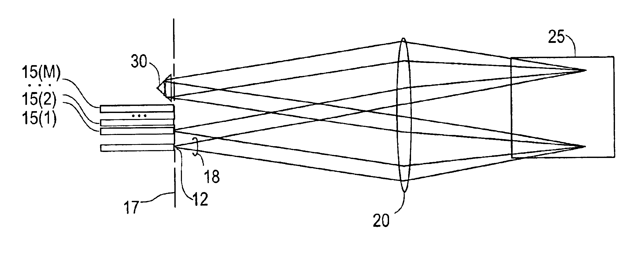
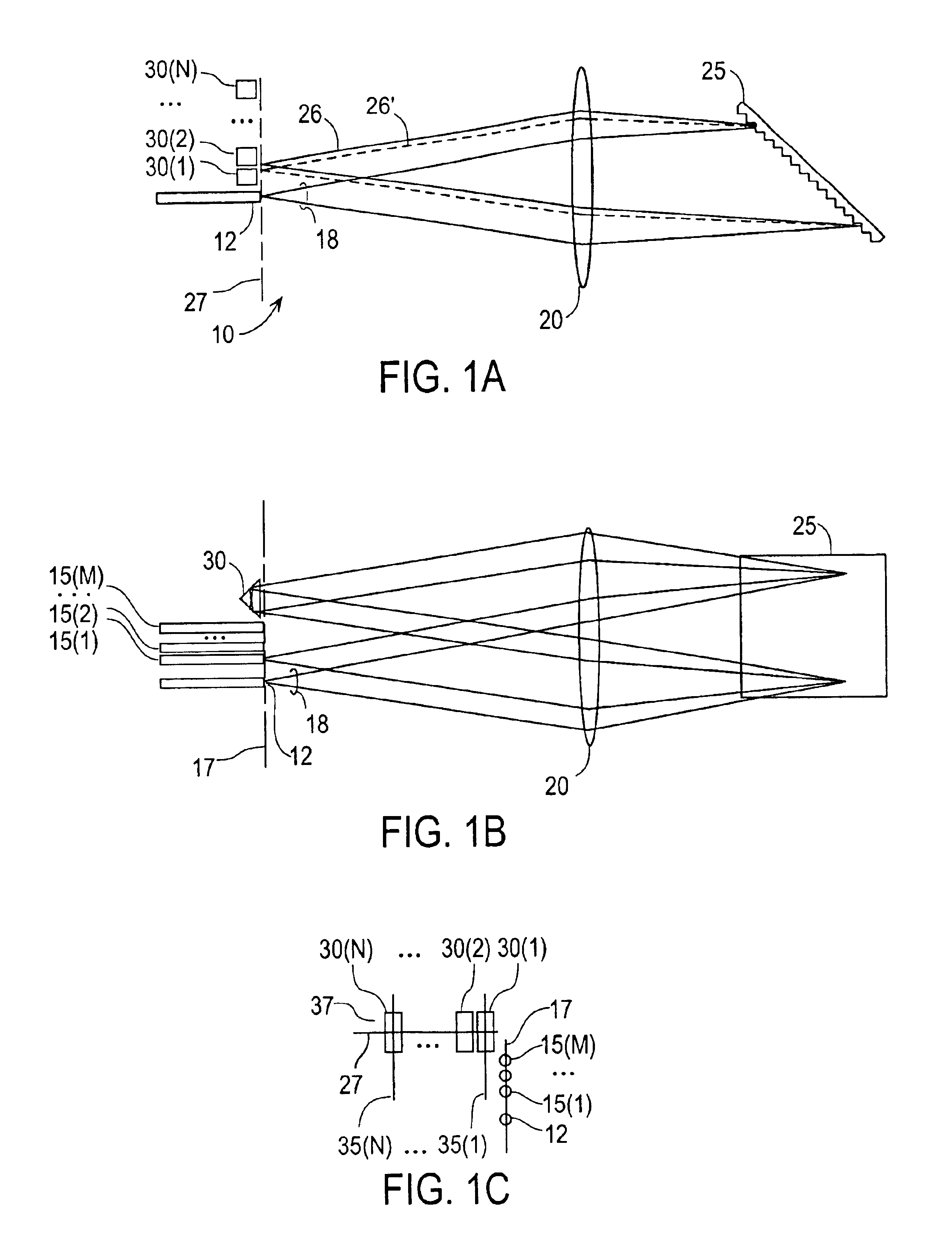
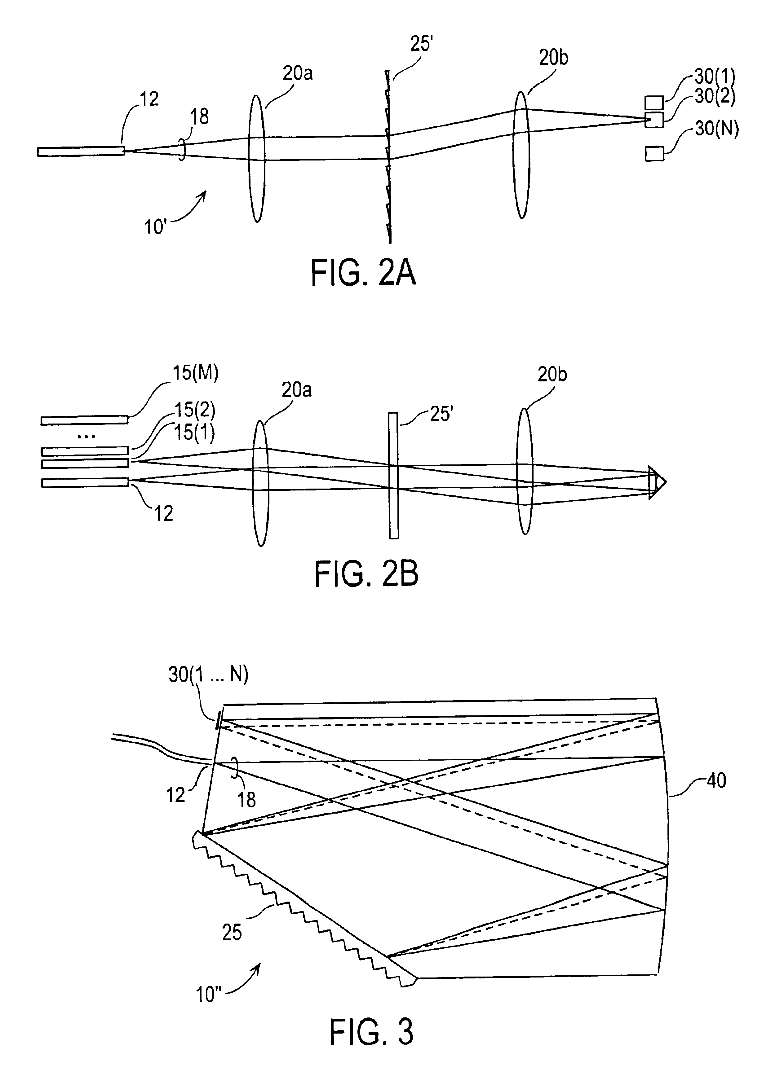
The present invention provides a wavelength router that allows for flexible and effective routing of spectral bands between input and output ports. The invention includes a free-space optical train and a routing mechanism. The optical train can include a dispersive element and can be of monolithic construction or air-spaced. The routing mechanism includes one or more routing elements that can be dynamically or statically changed to effect switching. The invention can route any spectral band to any output port and there is no requirement for the invention to be able to provide every possible routing. The routing elements can be retroreflectors or tiltable mirrors. The invention can be used in various applications such as optical communication systems, optical sensors, and optical imaging systems.

Problems solved by technology

The Internet and data communications are causing an explosion in the global demand for bandwidth.
This makes it difficult and expensive to scale DWDM networks using SONET / SDH technology.
This compound process is complex, very expensive, decreases system reliability and complicates system management.
The OXC in particular is a technical challenge.
Opto-mechanical switches, which offer acceptable optical specifications are too big, expensive and unreliable for widespread deployment.
New integrated solid-state technologies based on new materials are being researched, but are still far from commercial application.

Method used


Image

  • Wavelength router
  • Wavelength router
  • Wavelength router

Examples


Embodiment Construction

Introduction

The following description sets forth embodiments of an all-optical wavelength router according to the invention. Embodiments of the invention can be applied to network elements such as optical add-drop multiplexers (OADMs) and wavelength-selective cross-connects (WSXCs) to achieve the goals of optical networking systems.

The general functionality of the wavelength router is to accept light having a plurality of (say N) spectral bands at an input port, and selectively direct subsets of the spectral bands to desired ones of a plurality of (say M) output ports. In a specific implementation. N=80 and M=2 (i.e.. each of 80 wavelengths is selectively directed to either of two output ports). Most of the discussion will be with reference to dynamic (switching) embodiments where the routing mechanism includes one or more routing elements whose state can be dynamically changed in the field to effect switching. The invention also includes static embodiments in which the routing elem...


PUM

PropertyMeasurementUnit
differential path lengthaaaaaaaaaa
wavelengthaaaaaaaaaa

Abstract

A wavelength router that selectively directs spectral bands between an input port and a set of output ports. The router includes a free-space optical train disposed between the input ports and said output ports, and a routing mechanism. The free-space optical train can include air-spaced elements or can be of generally monolithic construction. The optical train includes a dispersive element such as a diffraction grating, and is configured so that the light from the input port encounters the dispersive element twice before reaching any of the output ports. The routing mechanism includes one or more routing elements and cooperates with the other elements in the optical train to provide optical paths that couple desired subsets of the spectral bands to desired output ports. The routing elements are disposed to intercept the different spectral bands after they have been spatially separated by their first encounter with the dispersive element.

Description

BACKGROUND OF THE INVENTIONThis application relates generally to fiber-optic communications and more specifically to techniques and devices for routing different spectral bands of an optical beam to different output ports. (or conversely, routing different spectral bands at the output ports to the input port).The Internet and data communications are causing an explosion in the global demand for bandwidth. Fiber optic telecommunications systems are currently deploying a relatively new technology called dense wavelength division multiplexing (DWDM) to expand the capacity of new and existing optical fiber systems to help satisfy this demand. In DWDM, multiple wavelengths of light simultaneously transport information through a single optical fiber. Each wavelength operates as an individual channel carrying a stream of data. The carrying capacity of a fiber is multiplied by the number of DWDM channels used. Today DWDM systems employing up to 80 channels are available from multiple manufa...

Claims


Application Information

Patent Timeline
Patent Type & Authority Patents(United States)
IPC IPC(8): G02B6/34H04J14/02H04Q11/00G02B6/35G02B26/08G02B6/293G02F1/313H04B10/43
CPCG02B6/29307G02B6/2931G02B6/29311G02B6/29313G02B6/29373G02B6/352H04J14/0206H04J14/0212H04J14/0213H04J14/0291H04Q11/0005G02B6/29308H04Q2011/0035G02B6/2938G02B6/29383G02B6/29395G02B6/29397G02B6/3522G02B6/3548G02B6/356H04J14/0204H04J14/0205H04J14/0283H04Q2011/0016H04Q2011/0024H04Q2011/0026
Inventor WEVERKA, ROBERT T.ROTH, RICHARD S.
Owner ALTERA CORP
Learn More