

Arrangement for implanting an endocardial cardiac lead
- Summary
- Abstract
- Description
- Claims
- Application Information
AI Technical Summary
Benefits of technology
Problems solved by technology
Method used
Image

Examples
first embodiment
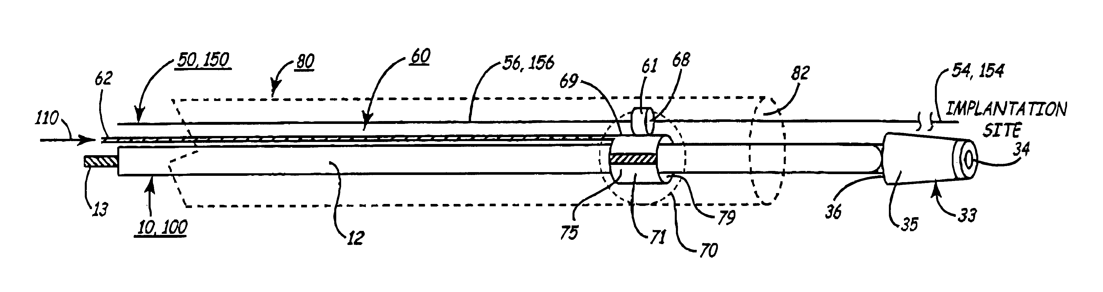
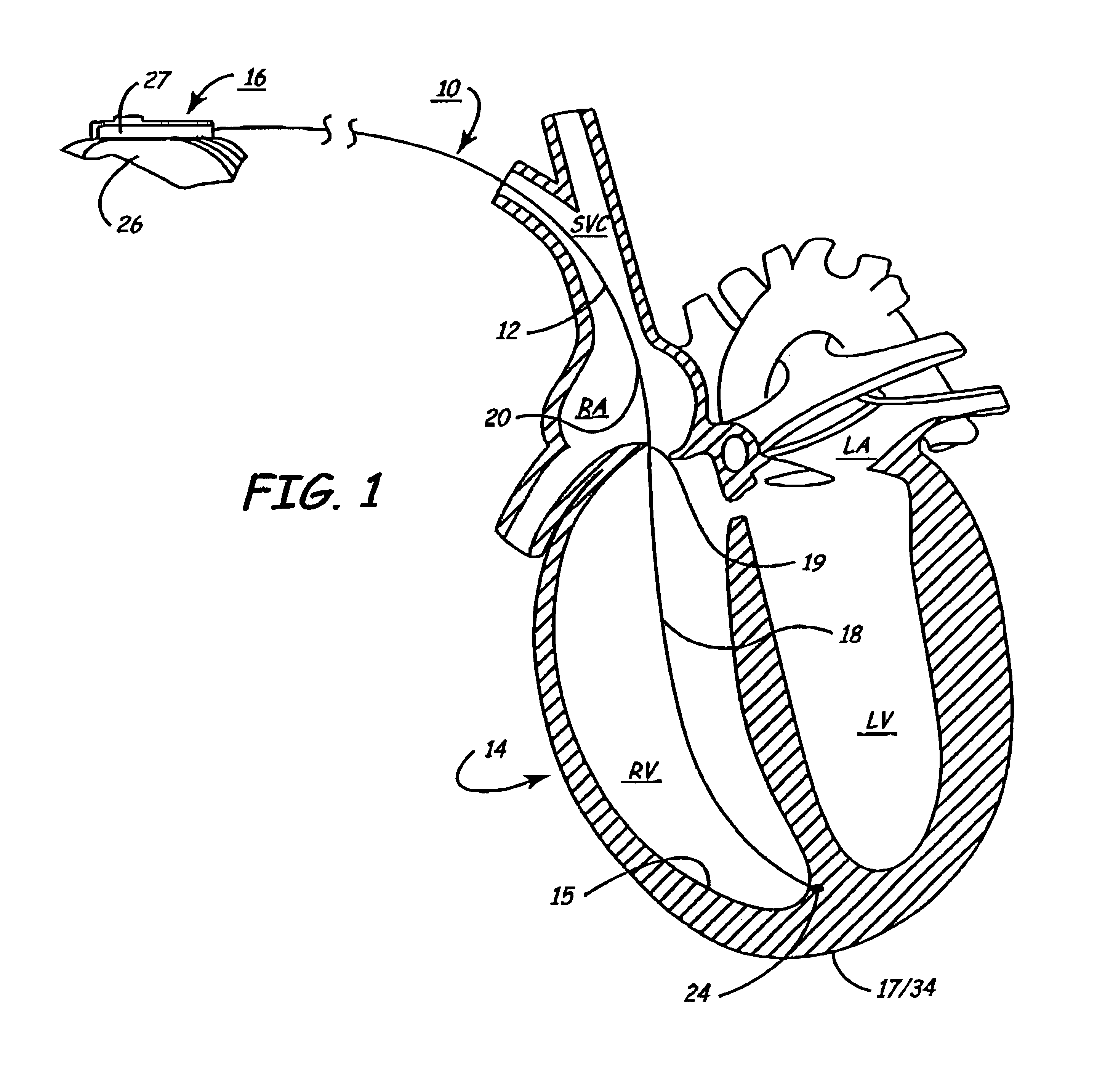
Typically, cardiac leads 10 and 100 are implanted in the prior art employing stiffening stylets or introducer catheters or other tools as described in detail above. FIG. 3 is a plan view of the introduction arrangement of the invention for introducing an endocardial cardiac lead 10 of the type illustrated in FIG. 1 into a right heart chamber and for attaching a fixation mechanism (e.g. helix 17 of FIG. 1) of the lead 10 to the myocardium or endocardium at one of the implantation sites 18, 19, 20, 24, etc., using the lead pusher 60. The arrangement of the lead pusher 60 and lead body facilitates the introduction and advancement of the endocardial cardiac lead 10 transvenously through an incision in the skin and within a patient's body to position the cardiac electrode at the cardiac implantation site.
In FIG. 3, a generic endocardial cardiac lead 10, 100 is depicted in relation to the lead pusher 60 and guiding means 50 of the first embodiment of the invention wherein the lead pusher ...
second embodiment
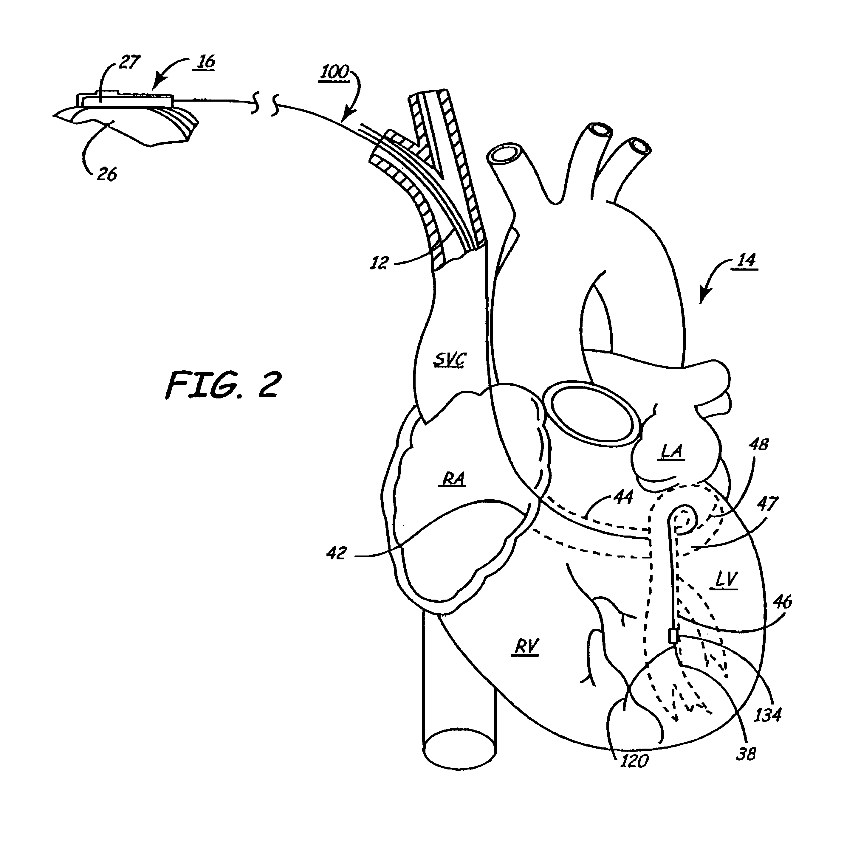
FIGS. 13-17 depict the arrangement of the present invention for introducing any of the leads 10, 10′, 10″ or 100 or other endocardial cardiac leads wherein the cardiac lead engaging means is part of or coupled with a distal portion of the lead body 12 and advanced by a lead pusher 160. In this embodiment, the simple guiding means 50, i.e., a guidewire, can be used to advantage, and consequently, this embodiment will be described hereafter assuming such use. But, it will be understood that the arrangement and method of this embodiment can also be used employing a more complex guidewire or micro-catheter 150 described above
In this embodiment, the cardiac lead engaging means comprises a feature, e.g. a lead engaging loop 171, formed at the lead distal end 33 having a guide body engaging lumen 179 for receiving and slidingly engaging the guide body 56 to allow the lead distal end 33 to be advanced distally over the guide body 56. In this case, the guide body tracking means 161 is a guid...
PUM
 Abstract
Description
Claims
Application Information