Methods and systems for calculating steam turbine radial clearance

a technology of radial clearance and steam turbine, which is applied in the direction of mechanical roughness/irregularity measurement, distance measurement, instruments, etc., can solve the problems of rotor blade tips striking the surrounding casing, reducing the efficiency of the turbine, and excessive regenerative rubs

Inactive Publication Date: 2005-03-15
GENERAL ELECTRIC CO
View PDF10 Cites 23 Cited by
  • Summary
  • Abstract
  • Description
  • Claims
  • Application Information

AI Technical Summary

Problems solved by technology

For example, if the clearance between the rotor blade tips and the surrounding casing is too large, flow may leak through the gap between the rotor blade tips and the surrounding casing, decreasing the turbine's efficiency.
However, if the clearance is too small, the rotor blade tips may strike the surrounding casing during certain turbine operating conditions.
A cold clearance, which is initially tight, can result in excessive regenerative rubs.
Over time, continued rubs may cause loss of material and/or a blunt or mushroomed seal tooth

Method used


Image

  • Methods and systems for calculating steam turbine radial clearance
  • Methods and systems for calculating steam turbine radial clearance
  • Methods and systems for calculating steam turbine radial clearance

Examples


Embodiment Construction

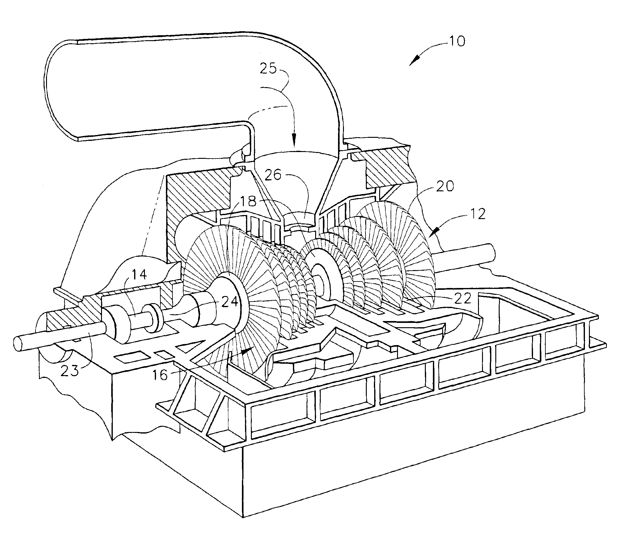
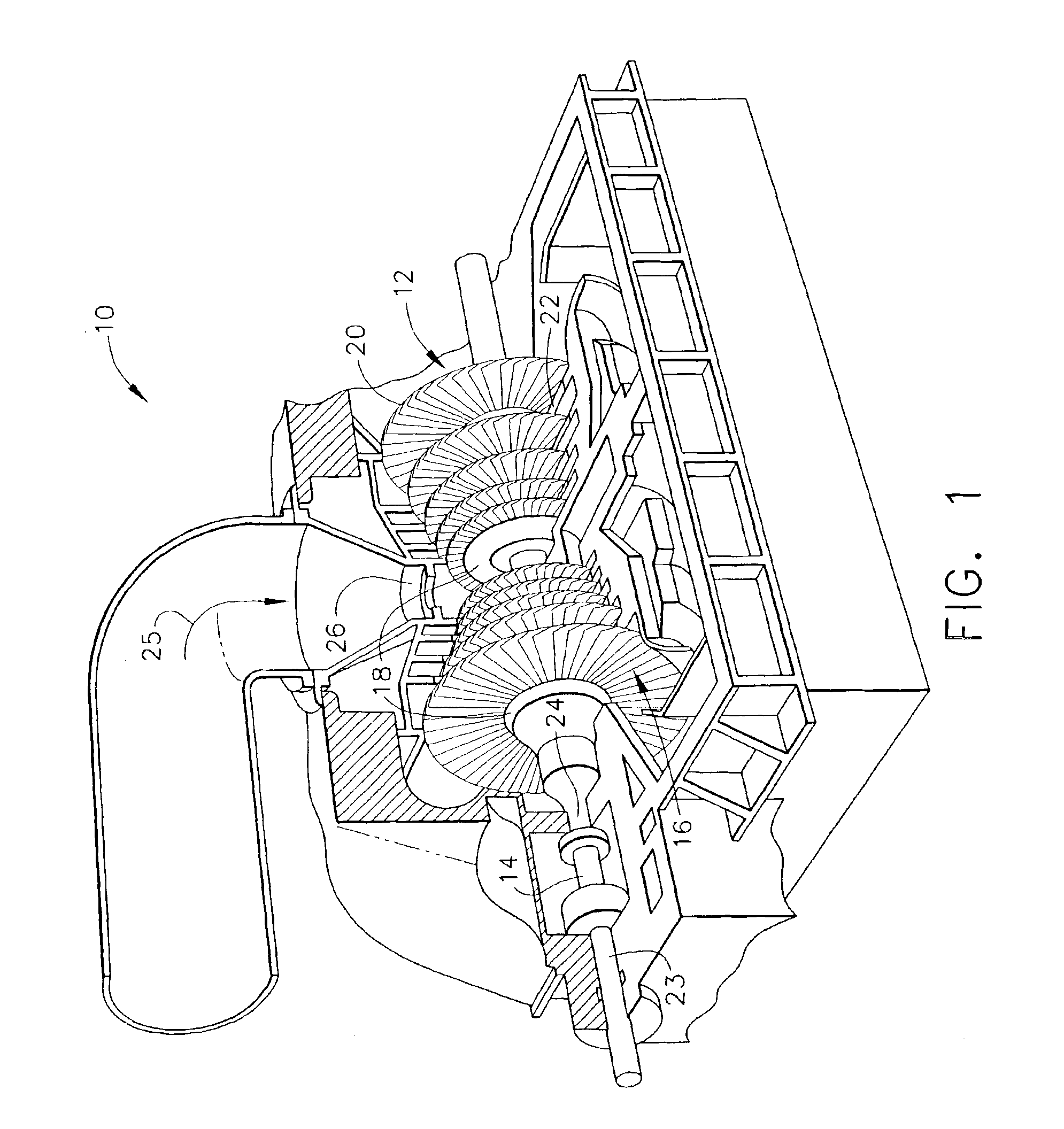
FIG. 1 is a perspective partial cut away view of an exemplary steam turbine 10 including a rotor 12 that includes a shaft 14 and a plurality of turbine stages 16. Turbine rotor 12 includes a plurality of axially spaced rotor wheels 18. A plurality of buckets 20 are mechanically coupled to each rotor wheel 18. More specifically, buckets 20 are arranged in rows that extend circumferentially around each rotor wheel 18. A plurality of stationary nozzles 22 extend circumferentially around shaft 14 and are axially positioned between adjacent rows of buckets 20. Nozzles 22 cooperate with buckets 20 to form each turbine stage 16 and to define a portion of a steam flow path through turbine 10. Shaft 14 is supported and guided in rotation by a plurality of bearings 23 and 24.

In operation, steam 25 enters an inlet 26 of turbine 10 and is channeled through nozzles 22. Nozzles 22 direct steam 25 downstream against buckets 20. Steam 25 passes through the remaining stages 16 imparting a force on b...


PUM


Abstract

A method and a system for determining radial clearances in a rotating machine are provided. The rotating machine includes at least one shell, at least one rotor, and at least one stationary component. The method includes creating a finite element model for at least one component within the rotating machine, creating a cycle deck data file for the rotating machine, determining an initial clearance versus time, and determining an initial clearance versus location. The system includes a client system including a browser, a centralized database for storing machine information, and a server system configured to be coupled to the client system and the database wherein the server system is further configured to receive machine information from the client system, store finite element model information in the centralized database, track machine information, update the centralized database periodically with newly received machine information to maintain machine information, and provide machine information in response to an inquiry.

Description

BACKGROUND OF THE INVENTIONThis invention relates generally to rotating machinery, and more particularly to steam turbines, and methods and system for calculating steam path clearances in steam turbines.A steam turbine includes a steam path which typically includes, in serial-flow relationship, a steam inlet, a turbine, and a steam outlet. At least some known turbine rotor assemblies include a plurality of rows of blades coupled to a rotor wheel. The blades are arranged in axially-spaced stages that extend circumferentially around the rotor wheel. More specifically, each stage includes a set of stationary blades or nozzles, and a set of cooperating rotating blades, known as buckets. The tips of the rotating blades are surrounded by a turbine casing such that a radial gap is defined between the rotor blade tips and the casing.An operating efficiency of the turbine is at least partially dependent upon the radial clearance or gap between rotor blade tips and the casing. For example, if...

Claims


Application Information

Patent Timeline
IPC IPC(8): G01B5/28G06F15/00G06F17/50
CPCG06F17/5018G06F2217/04G06F30/23G06F2111/02
Inventor BARAN, ROBERT GERARDPALMER, GENE DAVIDLAVASH, JOHN CLELANDLATHROP, NORMAN DOUGLAS
Owner GENERAL ELECTRIC CO
Why Eureka
Try Eureka