
Alpha-alumina coated cutting tool

a technology of alumina coating and cutting tool, which is applied in the field of cutting tools, can solve the problems of extensive flaking of the alumina layer, and the processing of nodular cast iron is still considered a demanding metal working operation, and achieves the effect of reducing the risk of rusting and rusting

Inactive Publication Date: 2005-03-22
SANDVIK INTELLECTUAL PROPERTY AB
View PDF16 Cites 39 Cited by
  • Summary
  • Abstract
  • Description
  • Claims
  • Application Information

AI Technical Summary

Problems solved by technology

However, the machining of nodular cast iron is still considered to be a demanding metal working operation.
This is particularly obvious in heavy and interrupted machining operations where an α-Al2O3 coated tool often suffers from extensive flaking of the alumina layer from the tool substrate.

Method used


Image

  • Alpha-alumina coated cutting tool
  • Alpha-alumina coated cutting tool
  • Alpha-alumina coated cutting tool

Examples


example 1

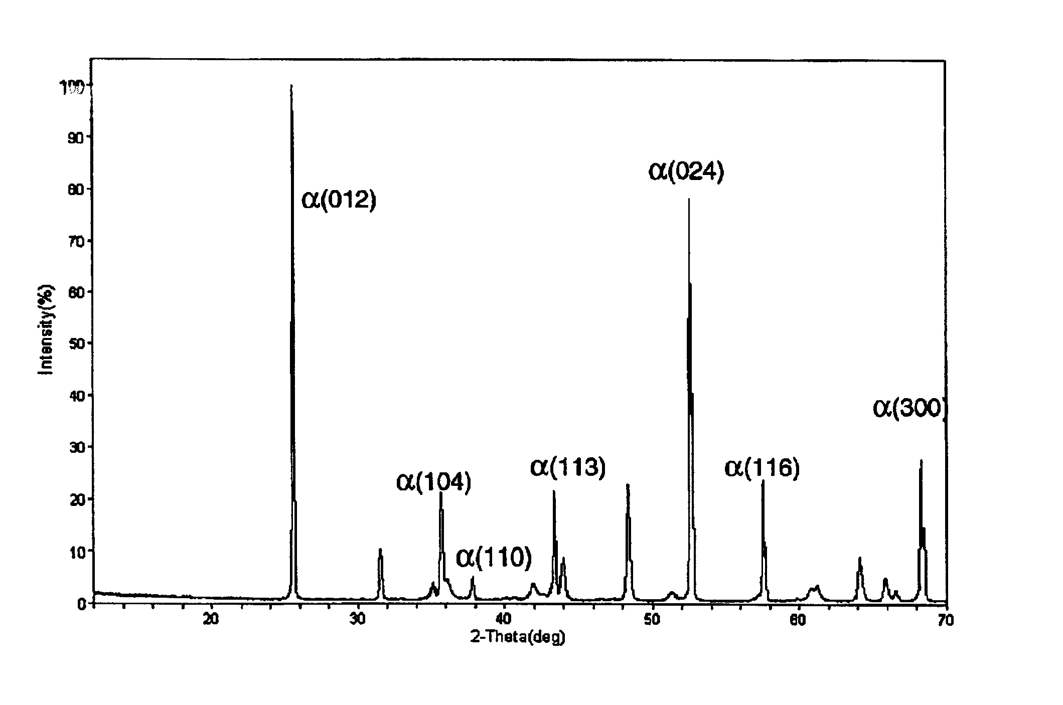
A) Cemented carbide cutting inserts with the composition 6.0 weight-% Co, and balance WC were coated with a 3 μm thick layer of TiCN in a standard CVD process. In subsequent process steps during the same coating cycle, a 7 μm thick layer of α-Al2O3 was deposited by the method described below.

A reaction gas mixture comprising H2, HCl and CO2 was first introduced into the CVD-reactor. The reaction gases were sequentially added in the given order. After a pre-set time AlCl3 was allowed into the reactor. During the deposition of Al2O3, H2S was used as a catalyst and ZrCl4 as texture modifying agent. The gas mixtures and other process conditions during the α-Al2O3 deposition steps comprised:

Step 1.Step 2.CO25%  5%AlCl32%  2%ZrCl4—  1%H2S—0.3%HCl2%  6%H2BalanceBalancePressure55 mbar55 mbarTemperature1010° C.1010° C.Duration1 hour3 hours

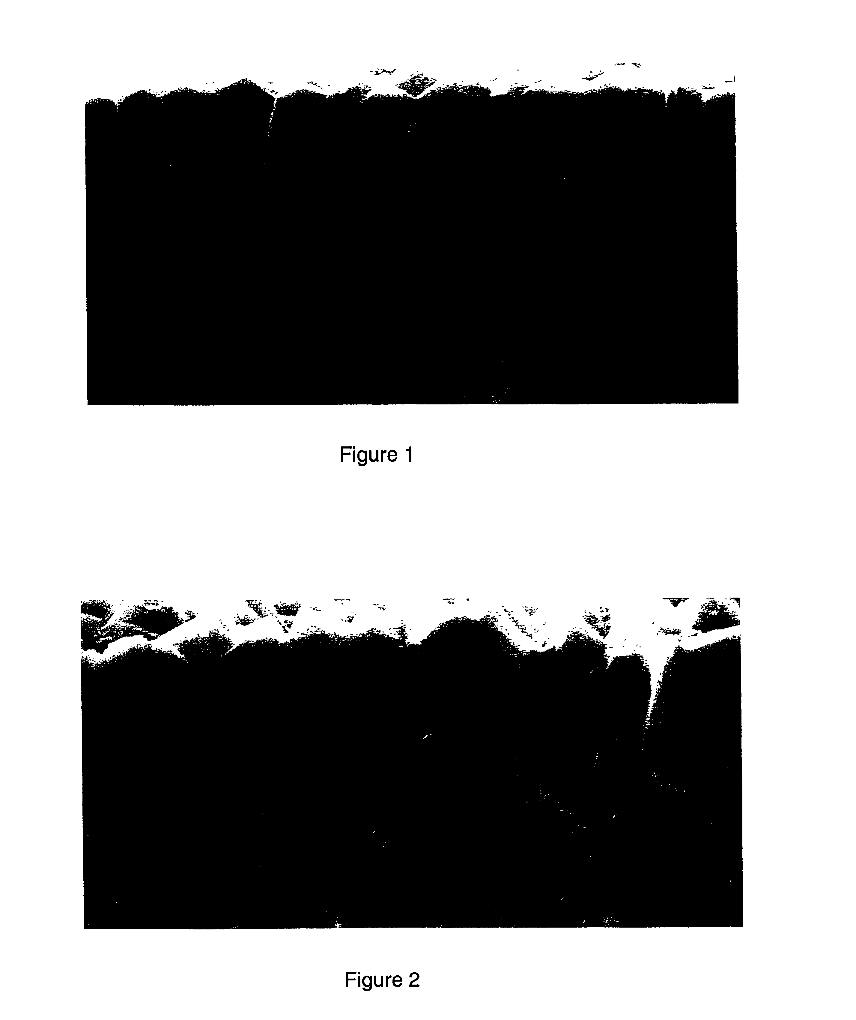
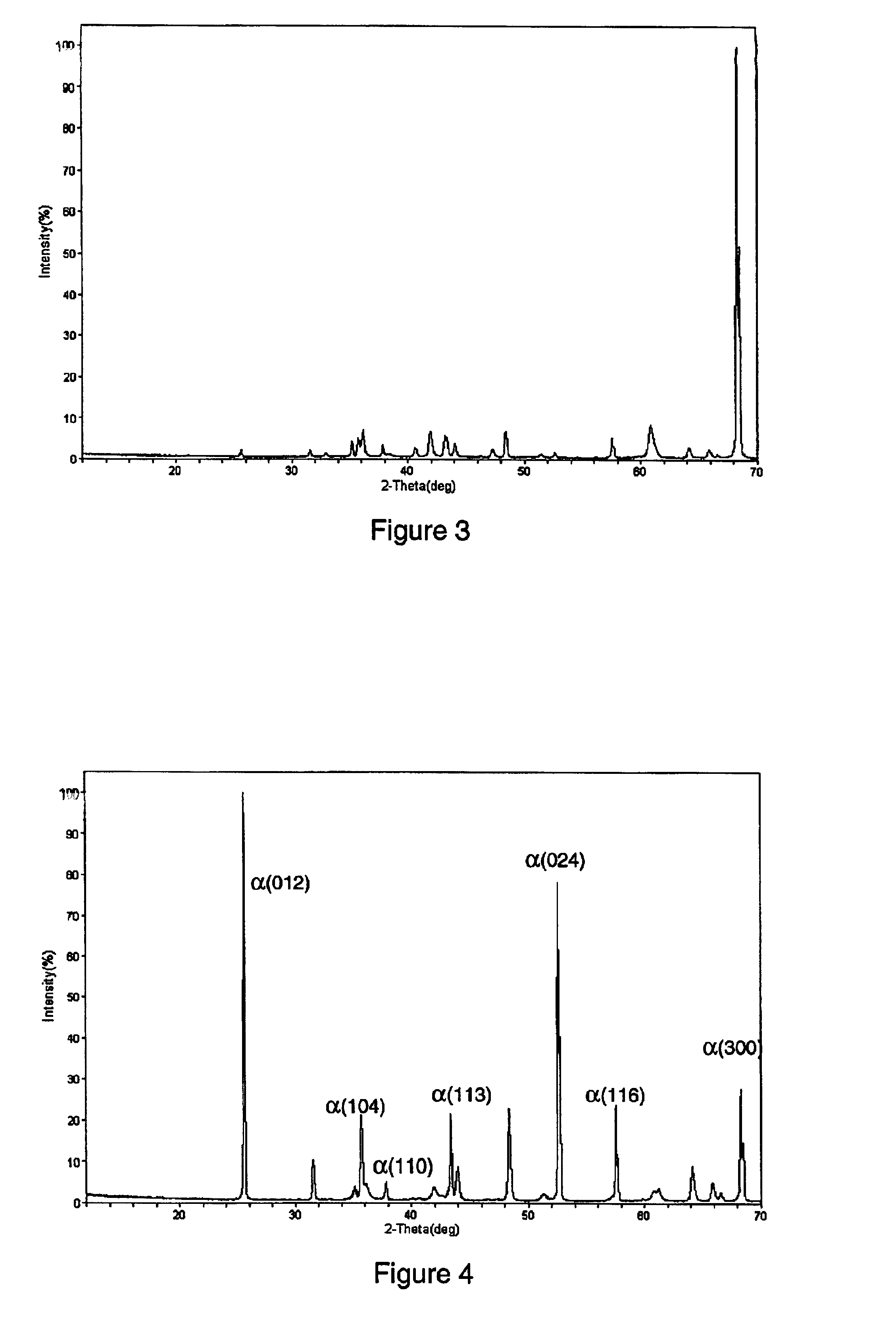
XRD-analysis showed a texture coefficient, TC(300), of 6.2 (average of ten inserts) of the single α-phase of the Al2O3-layer. SEM-micrographs showed a 7 μm...

example 2

Coated tool inserts from A), and B) were brushed using a standard production method in order to smoothen the coating surface. The cutting inserts were then tested with respect to edge line and rake face flaking in a turning operation, facing in nodular cast iron (AISI 60-40-18, DIN GGG40), a machining test which has proven to be a good benchmark test on the strength of the coating adhesion.

Cutting data:

Speed=250 m / min,Depth of cut=2.0 mmFeed=0.2 mm / rev.

Coolant was used.

The results are expressed in the table below as percentage of the edge line in cut on which flaking of the coating has occurred, and furthermore, the rake face area subjected to flaking in relation to the total contact area between the rake face and the workpiece chip. The numbers shown in the table below are average values for 5 tested cutting edges.

CoatingEdge line flakingRake face flakingAccording to A 4%<1%According to B53%62%

FIGS. 5 and 6 show Light Optical Microscope (LOM) micrographs of worn cutting edges ...


PUM

PropertyMeasurementUnit
Percent by massaaaaaaaaaa
Thicknessaaaaaaaaaa

Abstract

A coated cutting tool is composed of one or more layers of refractory compounds of which at least one layer is single-phase α-alumina with a pronounced columnar grain-structure and strong texture in the [300]-direction. The alumina layer is preferably deposited by CVD (Chemical Vapor Deposition) and the preferred microstructure and texture are achieved by adding a second metal halide, and a texture modifying agent, to the reaction gas. When coated cemented carbide cutting tools according to the invention are used in the machining of steel or cast iron, several important improvements compared to prior art have been observed, particularly in the machining of nodular cast iron.

Description

This application claims priority under 35 U.S.C. §§ 119 and / or 365 to 0100520-6 filed in Sweden on Feb. 16, 2001 the entire content of which is hereby incorporated by reference.FIELD OF THE INVENTIONThe present invention relates to a cutting tool for metal machining. More particularly, the present invention relates to a tool having a substrate of cemented carbide, cermet or ceramics and on the surface of said substrate, a hard and wear resistant coating is deposited. The coating is adherently bonded to the substrate and covering functional parts of the tool. The coating is composed of one or more refractory layers of which at least one layer consists of strongly textured alfa-alumina (α-Al2O3).BACKGROUND OF THE INVENTIONIn the description of the background of the present invention that follows reference is made to certain structures and methods, however, such references should not necessarily be construed as an admission that these structures and methods qualify as prior art under t...

Claims


Application Information

Patent Timeline
IPC IPC(8): C04B41/50C04B41/45C04B41/52C04B41/87C04B41/89C23C16/40B23B27/14
CPCC04B41/009C04B41/52C04B41/87C04B41/89C23C16/403C04B41/5031C04B41/4531C04B41/5061C04B41/5068C04B41/5042C04B35/00Y10T428/265C04B2111/0025Y10T428/24355Y10T428/24975
Inventor M.ANG.RTENSSON, PER
Owner SANDVIK INTELLECTUAL PROPERTY AB
Learn More