Manifold for a fuel cell system

a fuel cell and manifold technology, applied in the field of manifolds for fuel cell systems, can solve the problems of increasing parasitic load, poor system efficiency, and significant energy loss in lines or conduits, and achieve the effects of reducing the loss of thermodynamic and fluid flow in the system, and reducing the size and weight of the fuel cell system

Inactive Publication Date: 2005-03-22
HYDROGENICS CORP
View PDF19 Cites 10 Cited by
  • Summary
  • Abstract
  • Description
  • Claims
  • Application Information

AI Technical Summary

Benefits of technology

The manifold according to the present invention provides an interface between the fuel cell stack and heat exchangers, pump, fans, compressors, reformers, humidifiers etc, as well as process gases and coolant delivery components. This configuration can provide a higher degree of system integration, and hence offers a number of advantages. First, flow channels embossed into the manifold eliminate the need for bulky hoses and fittings and therefore the size and weight of the fuel cell system is considerably reduced. Moreover, thermodynamic and fluid flow related losses in the system are reduced, thus improving system efficiency, response to transient conditions and system control. In addition, since piping is minimized, control and maintenance of the system is simplified. Utilizing the invention minimizes all of the aforementioned difficulties because the compact nature of the manifold allows fuel cell systems to be developed for applications where strict size and weight constraints exist.
Fuel cell systems incorporating the present invention are inherently modular, and thus can be easily reproduced in large quantities at dedicated production facilities. Furthermore, the manifold of the present invention can be manufactured using currently available, inexpensive materials, which makes it suitable for manufacturing and mass production.

Problems solved by technology

These peripheral devices require extensive piping and associated hardware, all of which leads to poor system efficiency.
This results from significant energy losses occurring in lines or conduits as more power must be made available for supplementary devices such as pumps, fans, saturators etc, and hence the parasitic load is increased.
In addition, hoses, pipes, valves, switches and other fittings increase the overall weight and size of the fuel cell system and complicate the commercial application thereof.
This complexity poses problems in many applications, such as vehicular applications, where it is desirable that the piping and weight of the fuel cell system be minimized since strict size constraints exist.
This requirement makes it even more difficult to apply conventional fuel cell systems to vehicular applications, where relatively long pathways through hoses, valves, etc., can prevent rapid transient response characteristics being obtained.
However, to the applicants' knowledge, there has yet to be disclosed any fuel cell system that solves this fundamental problem.

Method used


Image

  • Manifold for a fuel cell system
  • Manifold for a fuel cell system
  • Manifold for a fuel cell system

Examples


Embodiment Construction

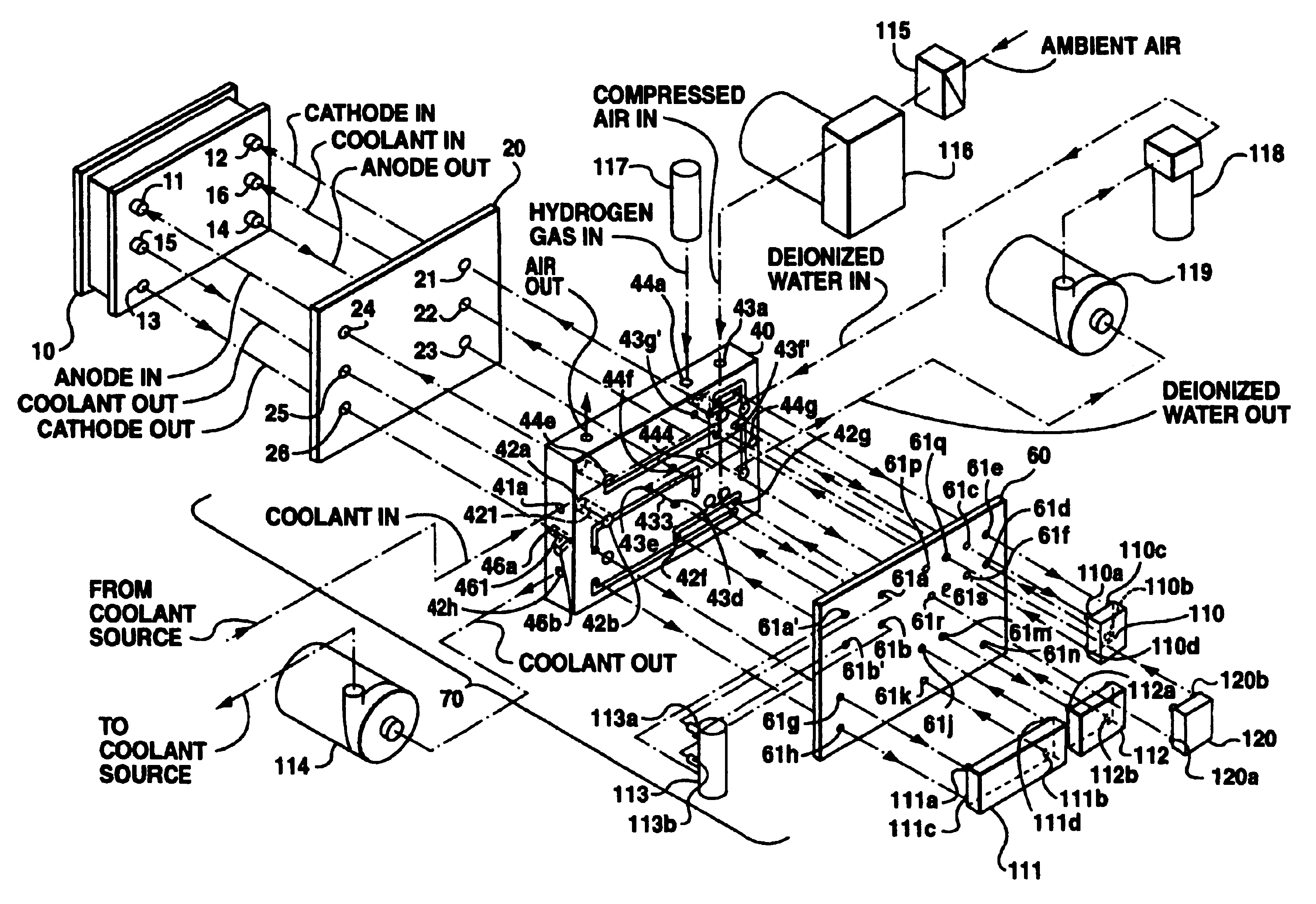
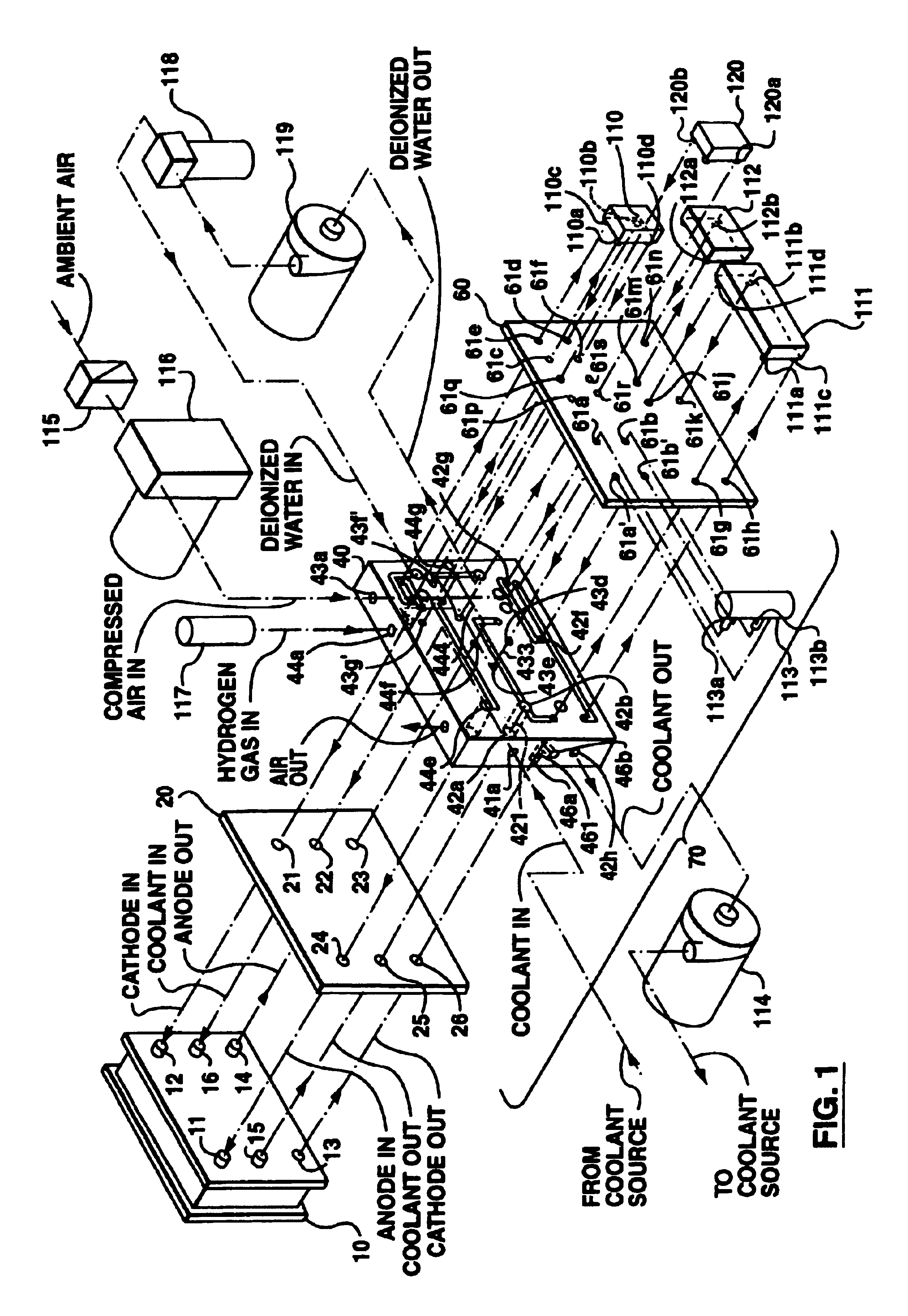
Now referring to FIG. 1, in which the basic arrangement of manifold assembly 70 according to the first embodiment of the present invention is shown, the manifold assembly 70 comprises of three individual plates. FIG. 1 also shows a fuel cell stack 10 having three inlets and three outlets, specifically, an anode inlet 11 for fuel gas, typically hydrogen, an anode outlet 14 for the fuel gas, a cathode inlet 12 for oxidant gas, typically oxygen or air, a cathode outlet 13 for oxidant gas, a coolant inlet 16 and a coolant outlet 15. It should be appreciated that the fuel cells in the fuel cell stack can be any type of fuel cell, such as, proton exchange membrane fuel cells, solid oxide fuel cells, direct methanol fuel cells, etc. The type of the fuel cells will not affect the design of the manifold according to the present invention.

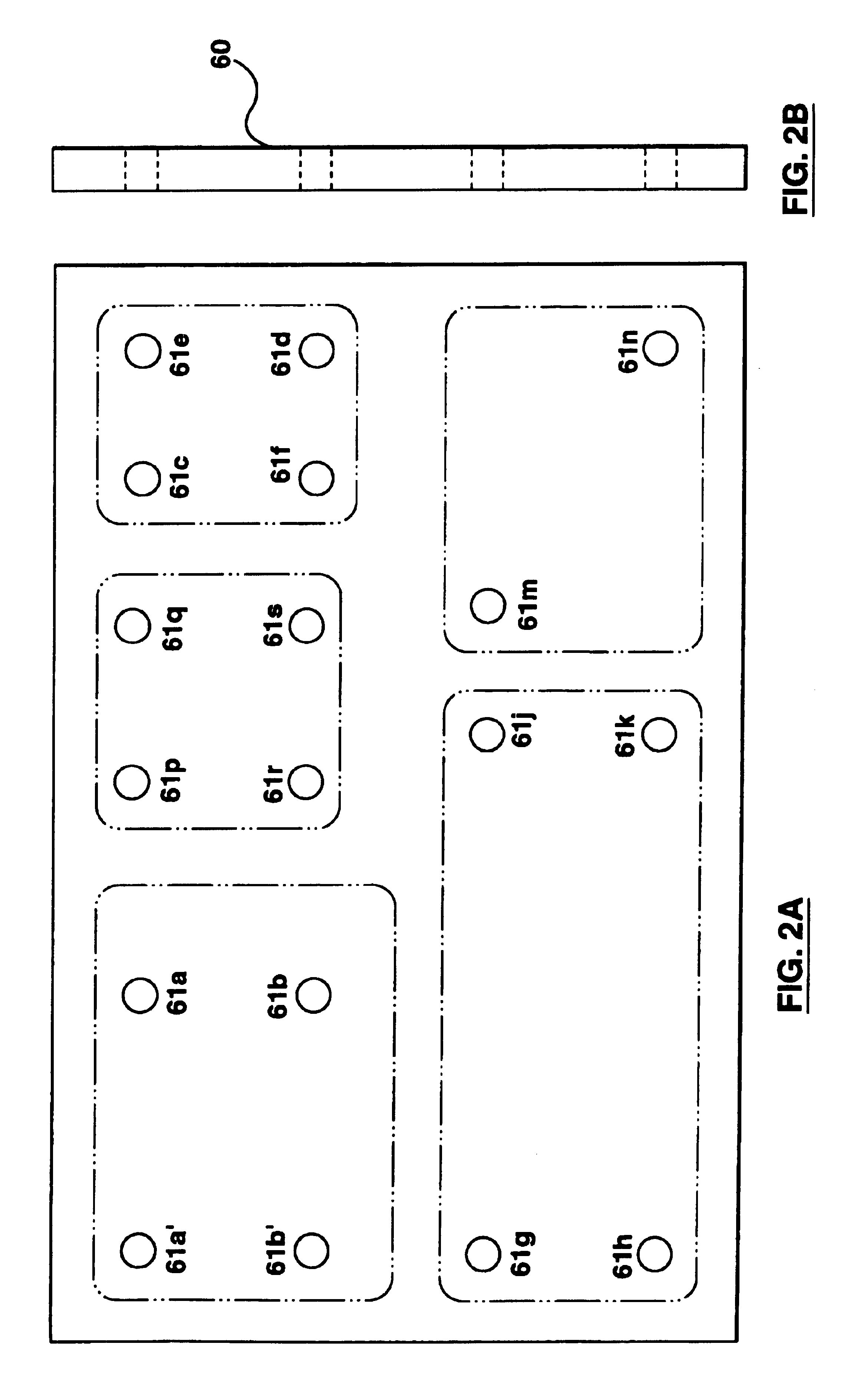
In this embodiment, the manifold assembly 70 has three plate layers, namely a front plate 60, a middle plate 40 and a back plate 20. The back plate 20 is fo...


PUM

PropertyMeasurementUnit
electromotive forceaaaaaaaaaa
electrical currentaaaaaaaaaa
electrical poweraaaaaaaaaa

Abstract

A manifold for a fuel cell system comprises a plurality of first ports for connecting to fuel cell peripherals; a plurality of ports for connecting to a fuel cell stack; and a plurality of fluid passages within the manifold in communication with the said plurality of ports connecting to the fuel cell peripherals and with the first and second ports for providing, communication of fluids between the fuel cell stack and fuel cell peripherals. The manifold provides a higher degree of system integration, considerably reduced piping, fittings and associated hardware and hence generally reduces the size and weight of the fuel cell system. Thermal-fluid related system losses are also minimized.

Description

FIELD OF INVENTIONThis invention relates to a manifold for a fuel cell system, and more particularly relates to a manifold for mounting peripherals and piping to fuel cell stacks.BACKGROUND TECHNOLOGYFuel cells have been proposed as a clean, efficient and environmentally friendly source of power which can be utilized for various applications. A fuel cell is an electrochemical device that produces an electromotive force by bringing the fuel (typically hydrogen) and an oxidant (typically air) into contact with two suitable electrodes and an electrolyte. A fuel, such as hydrogen gas, for example, is introduced at a first electrode, i.e. anode where it reacts electrochemically in the presence of the electrolyte to produce electrons and cations. The electrons are conducted from the anode to a second electrode, i.e. cathode through an electrical circuit connected between the electrodes. Cations pass through the electrolyte to the cathode. Simultaneously, an oxidant, such as oxygen gas or ...

Claims


Application Information

Patent Timeline
Patent Type & Authority Patents(United States)
IPC IPC(8): H01M8/02H01M8/24H01M8/00H01M8/04H01M8/10
CPCH01M8/04089H01M8/2485H01M8/04007Y02E60/50H01M8/04126H01M8/2484H01M8/24H01M8/0267
Inventor CARGNELLI, JOEYE, JIANMING
Owner HYDROGENICS CORP
Why Eureka
Try Eureka