Flexible telecommunications cable for outside plant equipment

a telecommunications cable and flexible technology, applied in the direction of cable termination, cable inlet sealing means, electric cable installation, etc., can solve the problems of inconvenient or even impossible to bend the extremely stiff cable, inconvenient to connect to the outside plant equipment, and extremely stiff cable, etc., to overcome the stiffness, facilitate the adjustment of alignment, and increase the flexibility of the cable

Inactive Publication Date: 2005-03-22
SPECIAL PRODS
View PDF7 Cites 10 Cited by
  • Summary
  • Abstract
  • Description
  • Claims
  • Application Information

AI Technical Summary

Benefits of technology

The present invention solves the above-described and other problems and provides a distinct advance in the art of enclosures for telecommunications, signaling, and similar electronic equipment. More particularly, the present invention provides a telecommunications cable or cable section for connection with telecommunications or signaling equipment or other outside plant equipment, wherein the cable comprises a braided or mesh protective sheathing, rather than solid metal protective sheathing or armor, that greatly increases the cable's flexibility and facilitates accommodating alignments or orientations of up to approximately 180° between the cable and the outside plant equipment. Thus, the present invention overcomes the stiffness associated with prior art armored cable without sacrificing electromagnetic interference (EMI) protection, signal shielding, or tensile strength. Additionally, the present invention maintains any pressurization that may be employed to prevent penetration of moisture or fine particles.

Problems solved by technology

Due to signal propagation limitations, these digital services require special electronic equipment, including electronic signal repeaters and doublers, located at or within specific distance intervals from a provider's central office and operable to repeat signals for end-users who would otherwise be outside of the signal propagation limits.
Unfortunately, solid metal protective sheathing also makes the cable extremely stiff and inflexible.
While stiff cable may be useable for long straight runs, it can make connecting to the outside plant equipment extremely difficult.
Unfortunately, it is often extremely difficult, time-consuming, and inconvenient or even impossible to bend the extremely stiff cable in a sufficiently tight radius so as to accomplish the connection.

Method used


Image

  • Flexible telecommunications cable for outside plant equipment
  • Flexible telecommunications cable for outside plant equipment
  • Flexible telecommunications cable for outside plant equipment

Examples


Embodiment Construction

.

BRIEF DESCRIPTION OF THE DRAWING FIGURES

A preferred embodiment of the present invention is described in detail below with reference to the attached drawing figures, wherein:

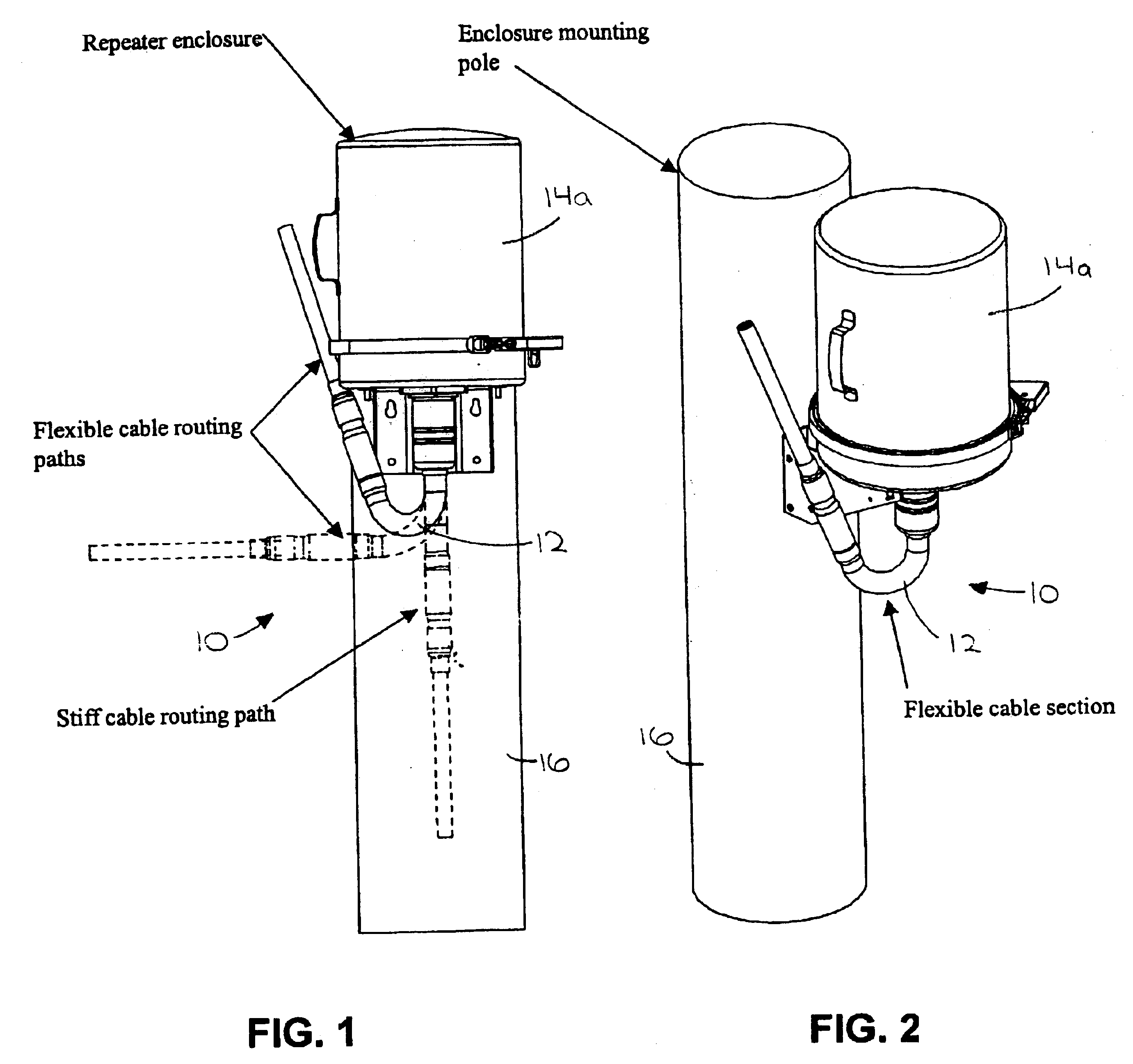
FIG. 1 is an elevation view of a preferred embodiment of the telecommunications cable of the present invention connected to a first type of telecommunications equipment enclosure mounted on a telephone pole, with separate instances of the cable shown in broken line to indicate possible orientations and range of flexibility;

FIG. 2 is an isometric view of the cable and the first type of telecommunications equipment enclosure of FIG. 1;

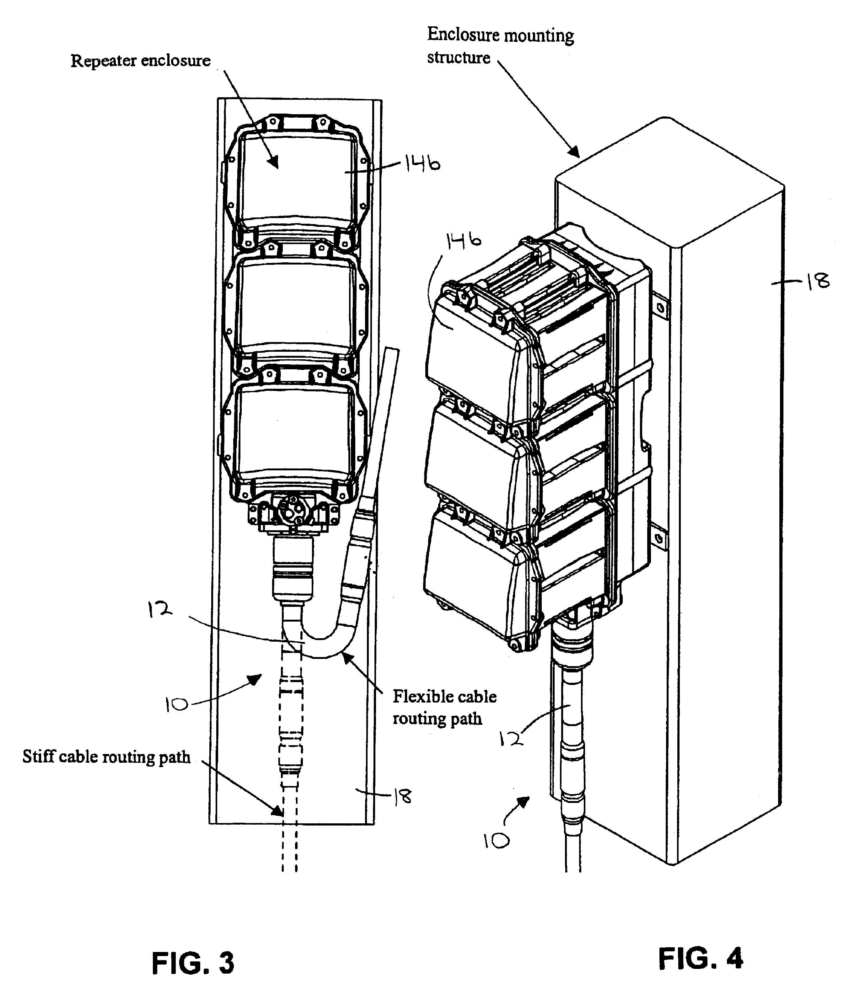
FIG. 3 is an elevation view of the cable connected to a second type of telecommunications equipment enclosure mounted on a column or wall within a manhole, with separate instances of the cable shown in broken line to indicate possible orientations and range of flexibility;

FIG. 4 is an isometric view of the cable and the second type of telecommunications equipment enclosure of FIG. 3;...


PUM


Abstract

A telecommunications cable section (12) for connection with telecommunications or signaling equipment or other outside plant equipment, wherein the cable section (12) comprises a plurality of conductors (30) surrounded by an intermediate layer of corrugated material (32). A flexible braided or mesh protective sheathing (34) substantially surrounds the intermediate layer (32). The braided sheathing (34) is preferably a braided or mesh sock or tubular sleeve or sleeve of copper or other metal or material. An exterior layer of substantially moisture-proof shrinkable tubing (36) substantially surrounds the braided sheathing (34).

Description

BACKGROUND OF THE INVENTION1. Field of the InventionThe present invention relates to mechanisms and methods for facilitating connection of a telecommunications cable to outside plant equipment. More particularly, the present invention provides a telecommunications cable or cable section for connection with telecommunications or signaling equipment or other outside plant equipment, wherein the cable comprises a braided or mesh protective sheathing, rather than solid metal protective sheathing or armor, that greatly increases the cable's flexibility and facilitates accommodating alignments or orientations of up to approximately 180° between the cable and the outside plant equipment.2. Description of the Prior ArtIn the telecommunications industry, signal transmission equipment located between central offices and between central offices and end users is termed “outside plant” equipment. This equipment is connected to or interfaced with a system or network using cables or other transmis...

Claims


Application Information

Patent Timeline
Patent Type & Authority Patents(United States)
IPC IPC(8): H02G15/00H02G15/18H02G15/02H02G15/076H02G15/013
CPCH02G15/013H02G15/1806H02G15/076
Inventor SCHIFFBAUER, ROBERTMAROSFALVY, HANSHUTCHISON, RANDALL D.TAUBERT, TOMASZSMITH, KEVAN
Owner SPECIAL PRODS
Why Eureka
Try Eureka