Method for the transmission of signals in a bus system, superposed on a direct supply voltage

a bus system and transmission method technology, applied in the direction of communication cables, dc source parallel operation, total enclosed bus-bar installations, etc., can solve the problems of high frequency accuracy, large expense and effort required for such a bus system, and one module only able to exchange signals with the central unit. , to achieve the effect of convenient operation

Inactive Publication Date: 2005-03-22
CONTI TEMIC MICROELECTRONIC GMBH +1
View PDF8 Cites 46 Cited by
  • Summary
  • Abstract
  • Description
  • Claims
  • Application Information

AI Technical Summary

Benefits of technology

[0007]It is the object of the invention to provide an alternative method for the signal transmission between a central unit and a number of modules, superposed on a direct supply voltag

Problems solved by technology

A disadvantage of this arrangement is that only exactly one module can exchange signals with the central unit.
This, however, just like the U.S. Patent, would result in the disadvantage that an extremely high accuracy of the frequencies is required for the demodulation.
The expense and effort required for such a bus system is considerable.
In this context, it is found to be problematic that on the one hand the direct supply voltage and on the other hand the current input through the modules is known and constant for the recognition of the current modulated

Method used


Image

  • Method for the transmission of signals in a bus system, superposed on a direct supply voltage
  • Method for the transmission of signals in a bus system, superposed on a direct supply voltage
  • Method for the transmission of signals in a bus system, superposed on a direct supply voltage

Examples


Embodiment Construction

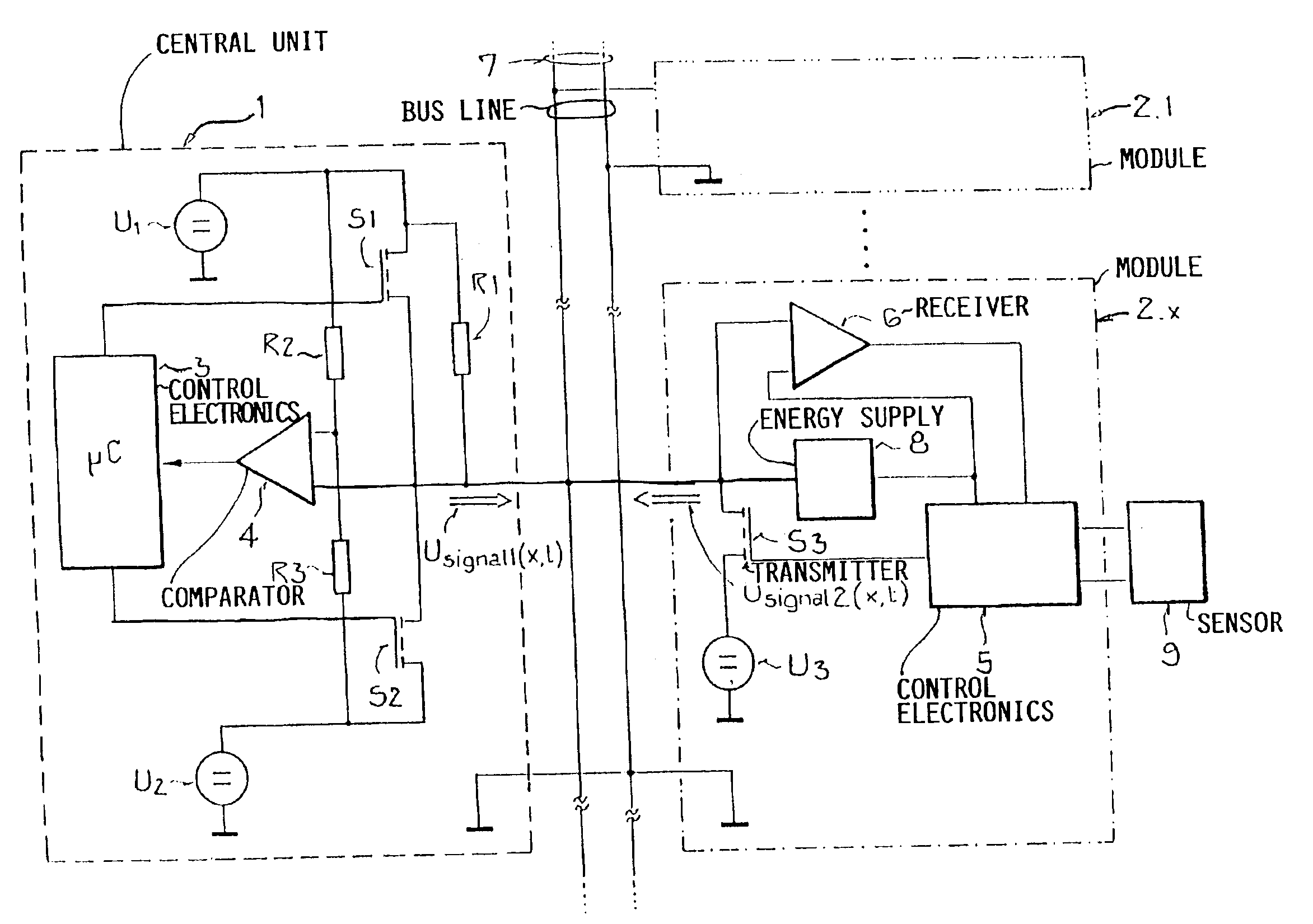
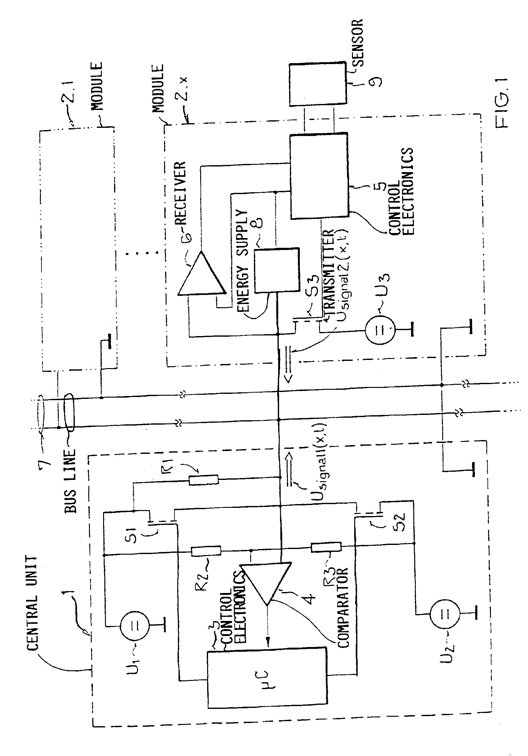
[0029]The FIG. 1 shows a circuit arrangement for carrying out the method with a bus system with a central unit 1 and a number of modules 2.1 to 2.n connected therewith via a bus line 7. For better clarity and comprehension, only the xth module 2.x of the modules 2.1 to 2.n is shown in detail, whereby the others are of course basically identically constructed, but generally comprise other downstream connected load elements, for example sensors 9.

[0030]The central unit 1 consists of a control electronics 3, for example a microcontroller, which carries out the control of the central unit 1 and therewith also the data transmission onto the bus line 7. Two voltage level sources U1 and U2 are provided for the similarly named voltage levels U1 and U2 being used, whereby one of these, and typically the larger one of the two and in this example U1, is used as the direct supply voltage. The second voltage level U2 could also be the ground potential, but an at least slightly higher potential i...


PUM


Abstract

Previously in a bus system, voltage signals were transmitted from the central unit to the modules, which could reply thereto by variation of the current input. A disadvantage thereby is the relatively high susceptibility to interference of the current input, which itself already must be kept relatively small due to the energy consumption, as well as the correspondingly high effort and expense for an error-free recognition of the signals transmitted from the modules in the central unit. It is now suggested, that the modules also answer to the central unit by means of voltage signals superposed on the direct supply voltage, whereby for the time duration of the signal transmission by the modules, the central unit provides the direct supply voltage to the bus line over a resistor, so that the voltage signal of the module can be detected in the central unit on the bus line on the side of the resistor facing away from the direct supply voltage. A preferred application for bus systems in motor vehicles, especially for a sensor data bus, is provided.

Description

FIELD OF THE INVENTION[0002]The invention relates to a method for the transmission of signals in a bus system between a central unit and a number of modules, wherein the signals are superposed on a direct supply voltage provided by the central unit onto at least one bus line. Thereby, the signal is additively supplemented to the direct supply voltage, i.e. superposed thereon, or the direct supply voltage is correspondingly modulated.BACKGROUND INFORMATION[0003]A method can be seen in the DE 196 22 685 A1, in which signals are exchanged between an evaluating unit serving as a central unit and an ignition device as a module. For the transmission of these signals from the evaluating unit to the ignition device, an alternating voltage signal is generated, which is superposed on a direct voltage that serves for the voltage supply. For replies from the ignition device, its current input is varied in a targeted manner (see col. 6, beginning at line 25 and claims 6 to 9 of the DE 196 22 685...

Claims


Application Information

Patent Timeline
IPC IPC(8): H04B3/54H04L12/10H04L12/40H04L25/02
CPCH04B2203/547H04L12/40006H04L12/403H04L12/4625H04L25/0272H04L25/028H04L2012/40273
Inventor BISCHOFF, MICHAELDEPPE, RUEDIGERFENDT, GUENTERHUBER, THOMASMUELLER, NORBERTNITSCHKE, WERNERRINKENS, JOHANNESSCHAEDLER, PETERSCHAEFFER, STEFANSTEINER, WERNER
Owner CONTI TEMIC MICROELECTRONIC GMBH
Why Eureka
Try Eureka