Supply voltage detection circuit

a detection circuit and supply voltage technology, applied in logic circuit coupling/interface arrangement, pulse technique, instruments, etc., can solve problems such as disturbance in the system, hot socket condition, and noisy vccn of uo power supply signal, and achieve rapid and effective detection of hot socket conditions, reduce the effect of leakage current on regular operation, and limit the size of leakage curren

Inactive Publication Date: 2005-03-22
ALTERA CORP
View PDF7 Cites 12 Cited by
  • Summary
  • Abstract
  • Description
  • Claims
  • Application Information

AI Technical Summary

Benefits of technology

In accordance with the present invention, a supply voltage detection circuit operates to detect a supply voltage condition, in particular a hot socket condition, when the voltage at any one of an IC device's power supply signal pins, e.g., an I/O power supply signal VCCN or a core power supply signal VCC, is below its steady state or expected level. Hot socket conditions may occur when an IC device is inserted in or removed from an electronic system while the system remai

Problems solved by technology

System architectures may rely upon multiple supply voltage schemes, some of which are noisy and some of which are quiet.
In particular, since bus controllers and other I/O circuitry are generally less sensitive and of lower speed than the core logic of an IC device, the UO power supply signal VCCN is often more noisy than a relatively quiet core power supply signal VCC (or VCCQ) for an IC device.
This growing variation in power supply levels within an electronic system presents significant difficulties in connection with the design of an efficient and effective “hot socket” detection circuit that can be used in IC devices having different power supply level requirements.
In these and other instances, the insertion or removal of a devic

Method used


Image

  • Supply voltage detection circuit
  • Supply voltage detection circuit
  • Supply voltage detection circuit

Examples


Embodiment Construction

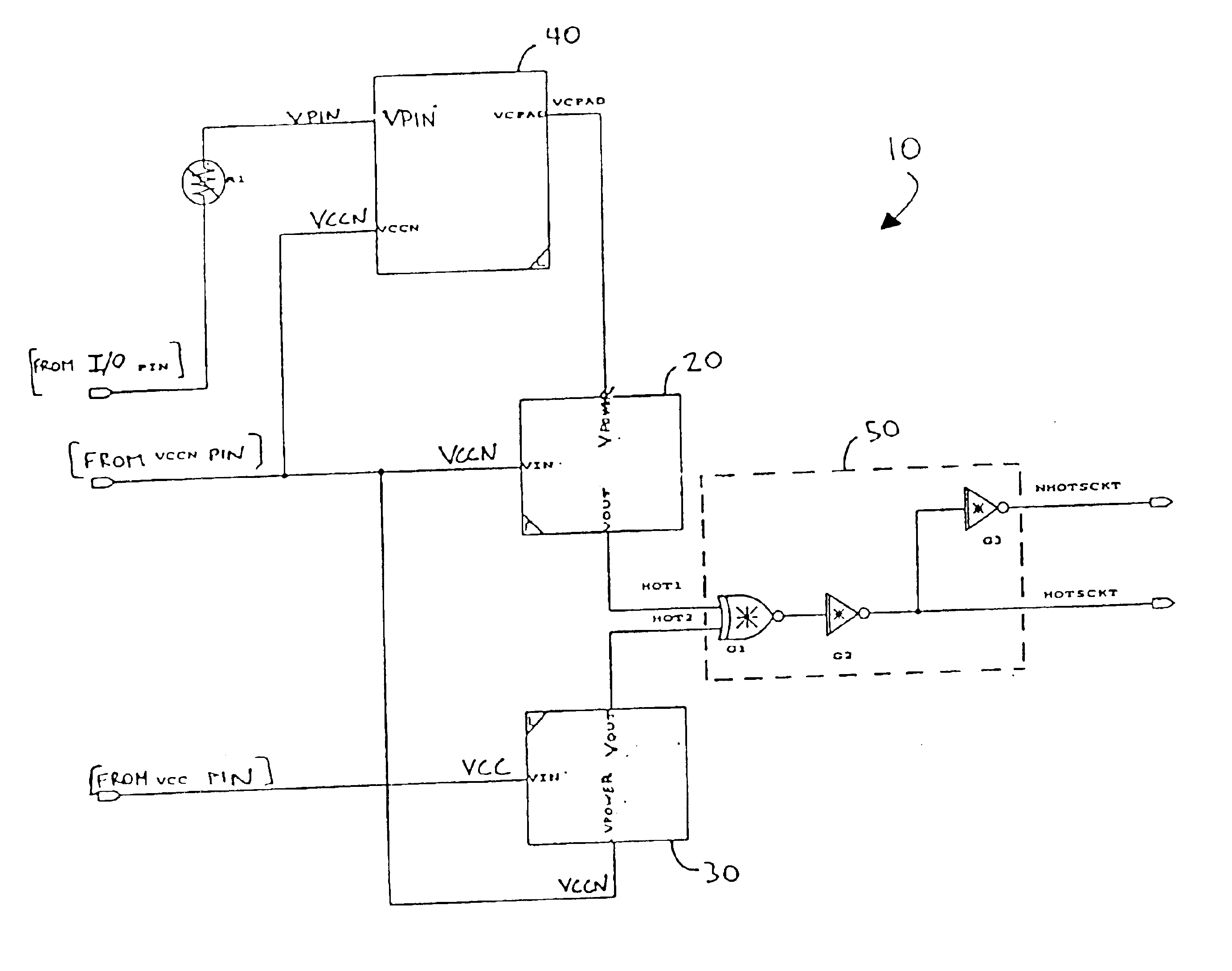
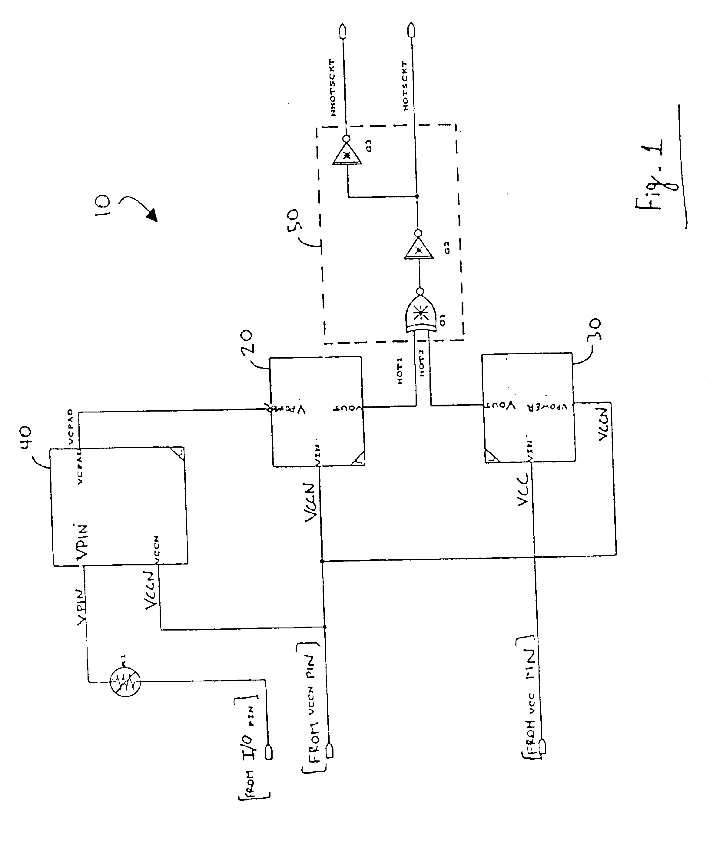
FIG. 1 is a circuit diagram of a supply voltage detection circuit 10 in accordance with an embodiment of the invention. Supply voltage detection circuit 10 is associated with an input / output (I / O) pin of an IC device, such as a PLD, in an electronic system (not shown). Typical applications of such systems include computer networking, data networking, telecommunications, instrumentation, and signal processing. However, the IC device may be included in any type of electronic system. Generally, the IC device has a number of I / O terminals, e.g., pins, for exchanging input and outputs signals with other devices in the system. The device may have other types of I / O terminals, such as bonding pads, solder balls, or bumps depending on its packaging. As used herein, an I / O terminal may refer to a terminal that is used exclusively as an input terminal, a terminal that is used exclusively as an output terminal, or a bidirectional terminal that can be configured to act either as an input or an ...


PUM


Abstract

A supply voltage detection circuit determines when the voltage for any one of the power supply signals received by an integrated circuit device is below its steady state level, as may occur during a hot socket condition when the device is inserted in or removed from a powered-on system. A first detection circuit determines when the first supply voltage level is below its steady state level, and a second detection circuit determines when the second supply voltage level is below its steady state level. A logic circuit provides a detected condition signal that disables current flow through an input/output terminal associated with the supply voltage detection circuit. The circuit is able to rapidly detect hot socket conditions for a wide range of power supply signal levels, including low supply signal levels, while limiting leakage current effects.

Description

FIELD OF INVENTIONThe present invention relates to a circuit for detecting supply voltage conditions, especially hot socket events that occur when an integrated circuit device is inserted or removed from an electronic system while the system remains powered on. More particularly, the present invention relates to a supply voltage detection circuit suitable for detecting hot socket conditions in mixed supply voltage systems having a wide range of power supply voltage levels.BACKGROUND OF THE INVENTIONDigital electronic systems are commonly implemented by combining and interconnecting several different integrated circuit (IC) devices such as processors, memory devices and programmable logic devices. Programmable logic devices (PLDs) are standardized ICs that are readily customizable to perform desired functions. The various IC devices typically communicate with one another by way of input / output (I / O) signals transmitted over a system bus. An UO power supply provides the necessary powe...

Claims


Application Information

Patent Timeline
IPC IPC(8): G06F1/28G06F1/24G06F1/32G01R19/155H03K3/356H03K17/22H03K19/0175
CPCG06F1/24H03K17/223G06F1/3203H03K3/356008G06F1/28G01R19/155
Inventor CHONG, YANSUNG, CHIAKANGWANG, BONNIENGUYEN, KHAIHUANG, JOSEPHWANG, XIAOBAOPAN, PHILIPKIM, IN WHANRANGAN, GOPICHANG, TZUNG-CHINSHUMARAYEV, SURGEY Y.WHITE, THOMAS H.
Owner ALTERA CORP
Why Eureka
Try Eureka