Direct electrical-to-optical conversion and light modulation in micro whispering-gallery-mode resonators

a technology of optical conversion and light modulation, applied in electromagnetic transceivers, semiconductor lasers, instruments, etc., can solve problems such as limit the performance of electronic devices, and achieve the effects of high quality factor, high quality factor, and efficient coupling

Inactive Publication Date: 2005-03-22
CALIFORNIA INST OF TECH
View PDF10 Cites 178 Cited by
  • Summary
  • Abstract
  • Description
  • Claims
  • Application Information

AI Technical Summary

Benefits of technology

The whispering-gallery-mode design of the resonator is used to provide an efficient coupling environment between the electrical modulation and the optical modulation. In absence of the electrical signal, the whispering-gallery-mode resonator, when properly designed, can achieve a high quality factor, which in turn produces narrow spectral linewidth of a supported whispering gallery mode. The electronic modulation by the electrical signal in resonance with the second and third ene

Problems solved by technology

For example, optical signals are generally immune to electromagnetic

Method used


Image

  • Direct electrical-to-optical conversion and light modulation in micro whispering-gallery-mode resonators
  • Direct electrical-to-optical conversion and light modulation in micro whispering-gallery-mode resonators
  • Direct electrical-to-optical conversion and light modulation in micro whispering-gallery-mode resonators

Examples


Embodiment Construction

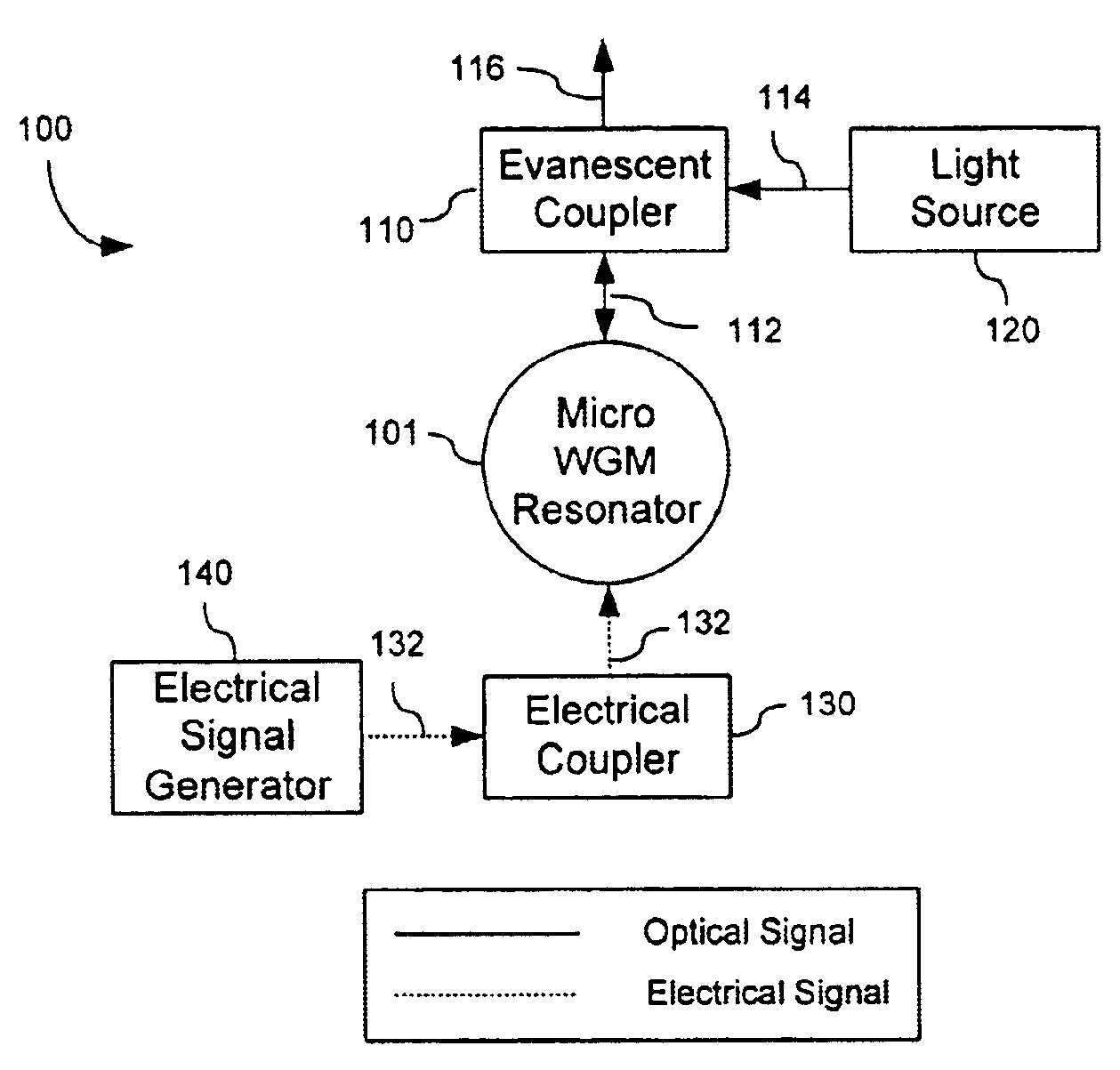
FIG. 1. shows one embodiment 100 of a direct electrical-to-optical conversion system based on a micro whispering-gallery-mode resonator 101 formed of a dielectric material with appropriate energy levels. In one implementation, the micro resonator 101 generally may be formed from at least a portion of a whole dielectric sphere that includes the equator of the sphere. Such a resonator can support a special set of resonator modes known as “whispering gallery modes” which are essentially electromagnetic field modes confined in an interior region close to the surface of the sphere around its equator and circulating by total internal reflection inside the axially symmetric dielectric body. Microspheres with diameters on the order of 10-102 microns have been used form compact optical resonators. Such resonators have a resonator dimension much larger than the wavelength of light so that the optical loss due to the finite curvature of the resonators can be small. The primary sources for opti...


PUM


Abstract

Techniques for directly converting an electrical signal into an optical signal by using a whispering gallery mode optical resonator formed of a dielectric material that allows for direct modulation of optical absorption by the electrical signal.

Description

BACKGROUNDThis application relates to conversion from an electrical signal to an optical signal and light modulation in response to an electrical signal.An electrical signal may carry certain information in either digital or analog form. The information can be imbedded in a property of the electrical signal such as the phase or the amplitude. The information in the electrical signal may be created in various ways, e.g., by artificially modulating the electrical carrier, or by exposing the electrical carrier to a medium which interacts with the carrier. In some applications, such information may be transmitted, processed, stored, received, or detected in the electrical domain. For example, electrical cables can be used to transmit information in electrical form; many electronic circuits or processors (e.g., microprocessors) can process information in electrical form; satellites, radars, and wireless telephones or other electronic devices can transmit or receive information in electro...

Claims


Application Information

Patent Timeline
IPC IPC(8): G02F1/01H01S3/081H01S3/083H01S5/00H01S5/10G02F1/17H04B10/40H04B10/43H04B10/50H04B10/516H04B10/54H04B10/60H04B10/61
CPCG02F1/011G02F1/17G02F1/0121H01S5/1075G02F2202/06G02F2203/15H01S3/083G02F2201/17
Inventor MALEKI, LUTELEVI, ANTHONY F. J.
Owner CALIFORNIA INST OF TECH
Why Eureka
Try Eureka