Method for on-board diagnosis of cold start emissions reduction control strategy

a technology of emissions reduction and on-board diagnosis, applied in the direction of electric control, machines/engines, instruments, etc., can solve the problem of increasing the difficulty of emissions control at startup

Active Publication Date: 2005-03-22
GM GLOBAL TECH OPERATIONS LLC
View PDF1 Cites 23 Cited by
  • Summary
  • Abstract
  • Description
  • Claims
  • Application Information

AI Technical Summary

Benefits of technology

A method and control system for verifying cold start emissions reduction control in a vehicle using an internal combustion engine utilizes measured engine speed or RPM (Revolutions per Minute) and commanded ignition timing. An actual thermal mass flow is estimated based on the measured engine speed. An actual thermal energy potential per unit mass is estimated from the commanded ignition timing. An estimated actual thermal energy is calculated by calculating a product of the actual thermal mass flow and the thermal energy potential.

Problems solved by technology

Emissions control is increasingly difficult at startup because the catalysts have not reached the warmed-up operating temperature.

Method used


Image

  • Method for on-board diagnosis of cold start emissions reduction control strategy
  • Method for on-board diagnosis of cold start emissions reduction control strategy
  • Method for on-board diagnosis of cold start emissions reduction control strategy

Examples


Embodiment Construction

The following description of the preferred embodiment is merely exemplary in nature and is in no way intended to limit the invention, its application, or uses.

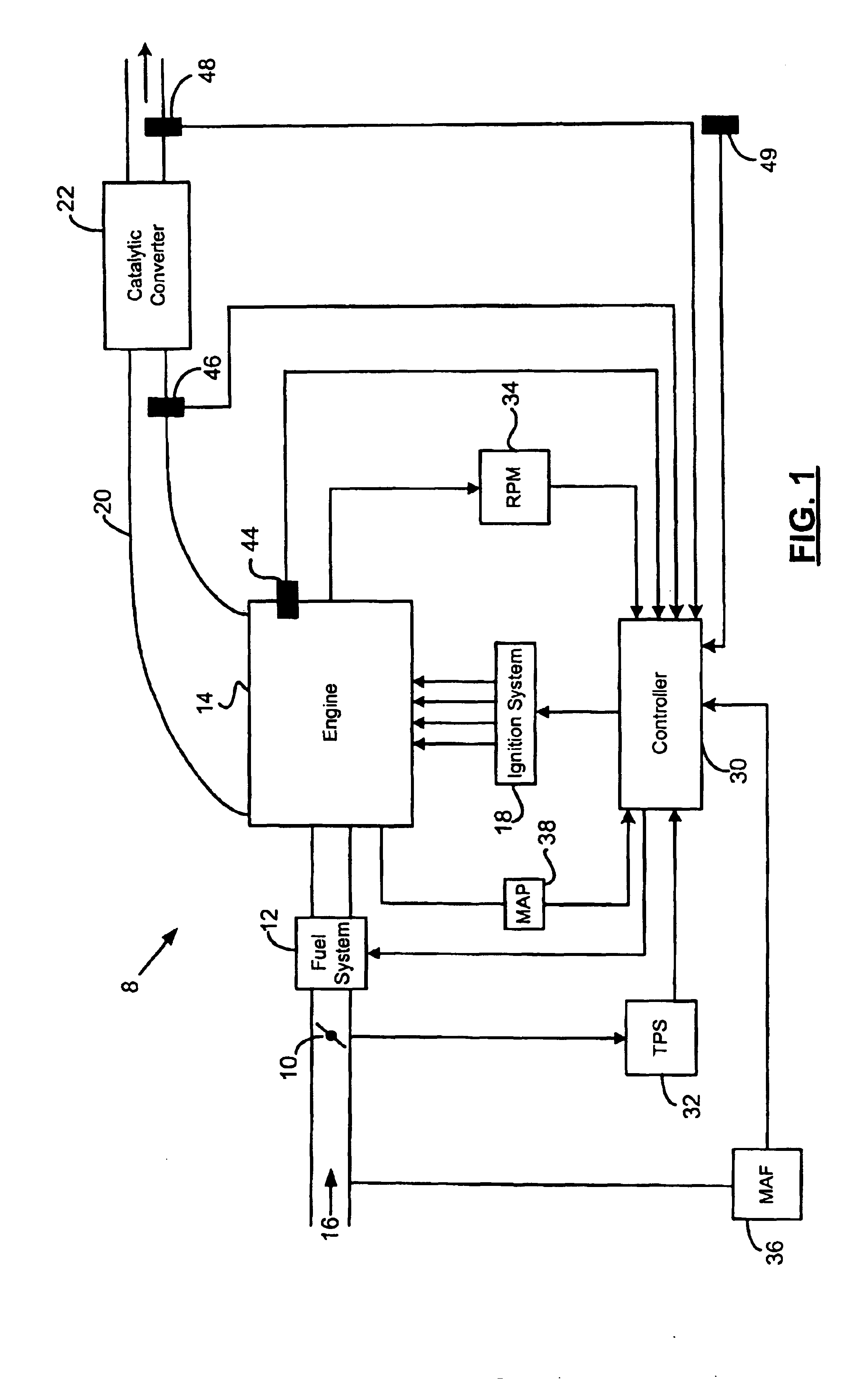
Referring to FIG. 1, an exemplary engine control system 8 is shown. A throttle 10 and a fuel system 12 control the air / fuel mixture that is delivered to an engine 14 through an intake 16. An ignition system 18 ignites the air / fuel mixture in the engine 14. Exhaust gas that is created by the combustion of the air / fuel mixture is expelled through an exhaust manifold 20. A catalytic converter 22 receives the exhaust gas from the exhaust manifold 20 and reduces the emissions levels of the exhaust gas.

A controller 30 communicates with various components of the engine control system 8, including but not limited to a throttle position sensor 32 (TPS), the fuel system 12, the ignition system 18, a mass airflow sensor 36 (MAF) and an intake manifold air pressure sensor 38 (MAP). The controller 30 receives a throttle position signal fro...


PUM


Abstract

A method and control system for verifying cold start emissions reduction control in a vehicle using an internal combustion engine utilizes measured engine speed and commanded ignition timing to calculate an estimated actual engine-out thermal energy flow. An expected thermal energy flow is calculated based on designed engine speed and ignition timing. A residual energy flow is calculated based on a difference between the estimated actual thermal energy flow and the expected thermal energy flow. Meanwhile, a system quality-weighting factor is calculated based on several measured engine parameters. A qualified energy flow residual is calculated based on the system quality weight and the residual energy flow. The qualified energy residual flow is accumulated, averaged based on the accumulated quality weight, and then filtered. Diagnostic control determines that if the cold start emissions reduction control is operating correctly based on the filtered averaged qualified energy flow residual comparing a predetermined range.

Description

FIELD OF THE INVENTIONThe present invention relates to engine control systems for vehicles, and more particularly to a diagnostic for monitoring a cold start emissions reduction control system.BACKGROUND OF THE INVENTIONCatalytic converters reduce exhaust gas emissions in vehicles using an internal combustion engine. A three-way catalytic converter includes a substrate with a coating of catalyst materials that stimulate the oxidation of hydrocarbon and carbon monoxide, and the reduction of nitrogen oxides, in the exhaust gas. The catalysts operate optimally when the temperature of the catalysts is above a minimum level and when the air / fuel ratio is stoichiometric. Stoichiometry is defined as an ideal air / fuel ratio, which is 14.7 to 1 for gasoline.It is desirable to optimize the air / fuel ratio in the engine for performance as well as emissions control. Emissions control is increasingly difficult at startup because the catalysts have not reached the warmed-up operating temperature. ...

Claims


Application Information

Patent Timeline
Patent Type & Authority Patents(United States)
IPC IPC(8): F02D41/02F02D41/14F02D41/06
CPCF02D41/0245F02D41/0255F02D41/064Y02T10/26F02D41/187F02D2200/0404F02D2200/0406F02D41/1441Y02T10/12
Inventor WANG, WENBOJESS, RICHARD B.HAMILTON, LYLE E.BOLSTRUM, DANIEL G.ROELLE, MATTHEW J.VAN GILDER, JOHN F.BELTON, DAVID N.AMANN, RICHARD W.FU, FANG-CHENG J.
Owner GM GLOBAL TECH OPERATIONS LLC
Why Eureka
Try Eureka