Disc driving apparatus

a technology of disc driving and discs, which is applied in the direction of instruments, optical beam sources, disposition/mounting of heads, etc., can solve the problems of reducing reproducing/recording accuracy, erroneous operation, and deterioration of so as to reduce thermal interference, reduce the lifetime of parts or elements, and high reliability

Inactive Publication Date: 2005-03-22
HITACHI CONSUMER ELECTRONICS CORP
View PDF2 Cites 16 Cited by
  • Summary
  • Abstract
  • Description
  • Claims
  • Application Information

AI Technical Summary

Benefits of technology

An object of the present invention is to provide a disc driving apparatus, wherein thermal interference is reduced between heat-generating elements which are disposed in close proximity with each other, in particular, in the optical pickup, so as to protect the heat-generating elements from deterioration leading to reduction in the lifetime thereof, thereby providing a disc during apparatus having a high reliability.

Problems solved by technology

However, in the above-described conventional arts 1 and 2, there is no disclosure concerning deterioration of the lifetime of parts or elements, erroneous operation, or a decrease in the reproducing / recording accuracy, accompanying a non-uniform local temperature distribution, due to thermal interference between adjacently disposed heat generating elements and / or heat generation of a heat-generating element.
Therefore, there is a possibility that, in a case where plural numbers of heat-generating elements are disposed at neighboring locations relatively close to each other, due to the thermal interference between the heat-generating elements, elements having a small heat generation amount and / or elements of low heat-resistance or endurance are affected with the thermal influences provided by other heat-generating elements, erroneous operation, and / or a decrease in the reproducing / recording accuracy.
Namely, in general, within a disc drive or apparatus equipped with an optical pickup, there are mounted a laser diode which generates heat when it performs a recording / reproducing operation, a laser driver circuit board, a high frequency module, and plural numbers of parts or elements, such as a driver coil for use in an objective lens driver, etc., to be connected thermally, in a pickup housing made of metal, and heat generation of those heat-generating elements causes a local non-uniform temperature distribution within the pickup housing, thereby causing thermal interference between those heat-generating elements.
Because of those heat-generating elements, the following problems are created(1) Thermal interference due to the close disposition of the heat-generating elements;(2) Thermal deformation due to a locally non-uniform temperature distribution;(3) A deterioration of the lifetime of elements due to heat; and(4) A local rise in temperature inside of the apparatus due to heat radiation from the elements functioning as a heat source, and erroneous operation or malfunction in a circuit system.

Method used


Image

  • Disc driving apparatus
  • Disc driving apparatus
  • Disc driving apparatus

Examples


first embodiment

First, an explanation will be given of a first embodiment according to the present invention with reference to FIGS. 1 to 3.

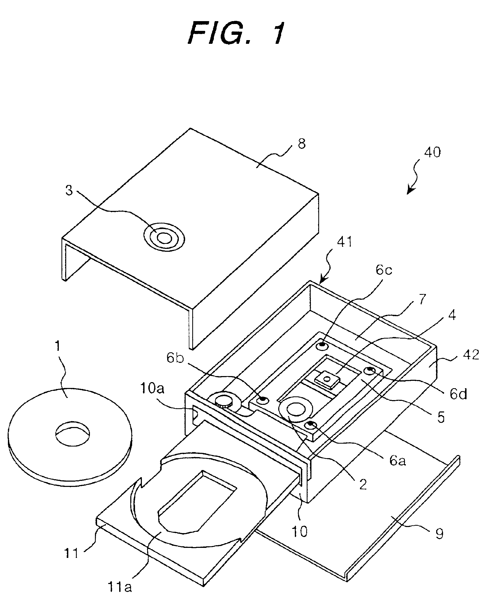
First of all, the overall structure of the disc driving apparatus according to the present embodiment and the operation thereof will be explained with reference to FIG. 1, which is an exploded perspective view of the disc driving apparatus according to the first embodiment of the present invention.

A disc driving apparatus 40, being a DVD-ROM apparatus corresponding to a CD-R / RW device, comprises a disc driver housing 41, a disc loading mechanism for carrying a disc 1 into and out of the disc driver housing 41, and a reproducing / recording mechanism for reproducing / recording information on the disc 1. This disc driving apparatus 40 is used therein. Further, the present invention is applicable to a device such as a CD-ROM drive, a DVD-RAM drive, etc.

The disc driver housing 41 has sidewalls 42 in a rectangular shape as seen in plane view, a mechanical base 7 formed...

second embodiment

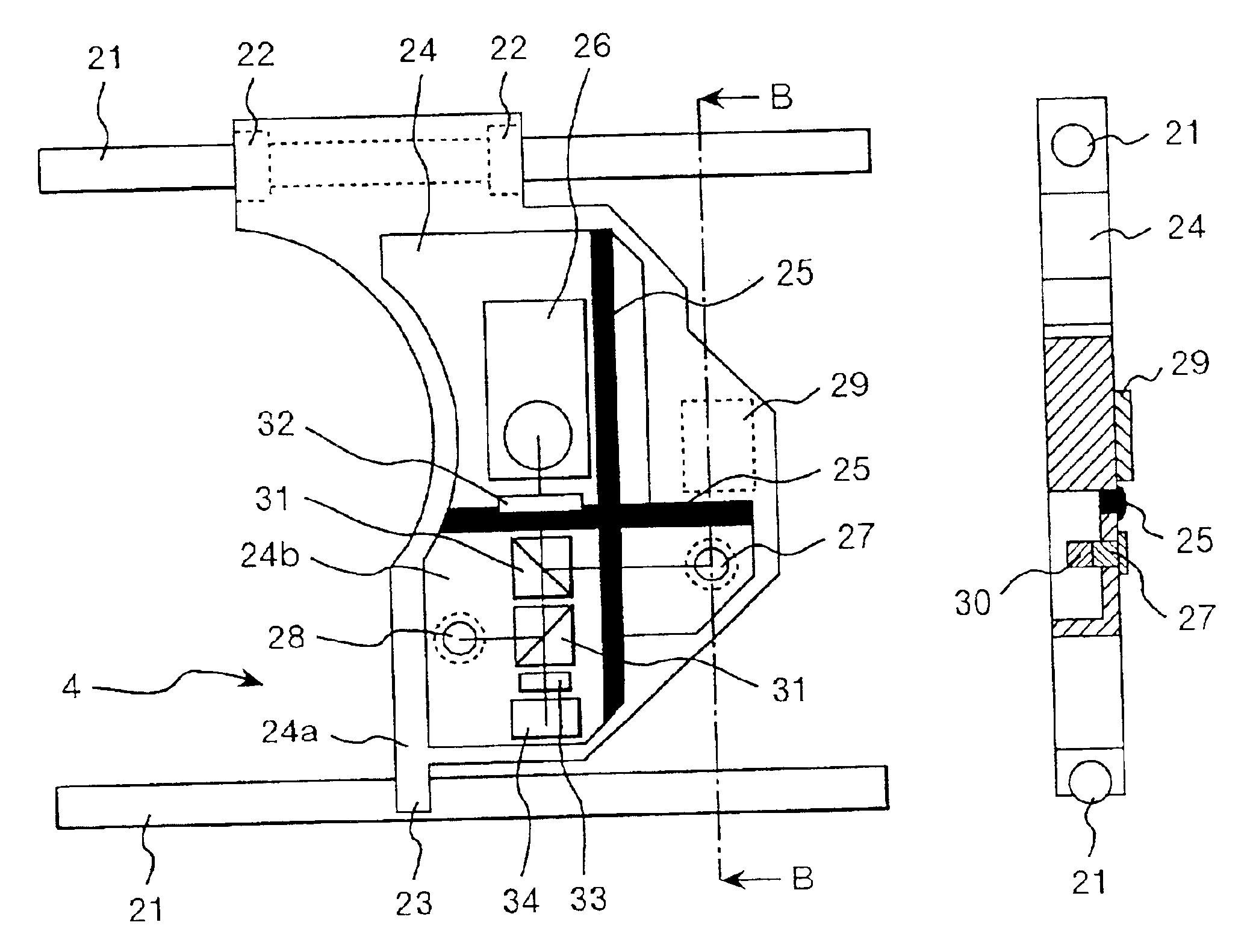
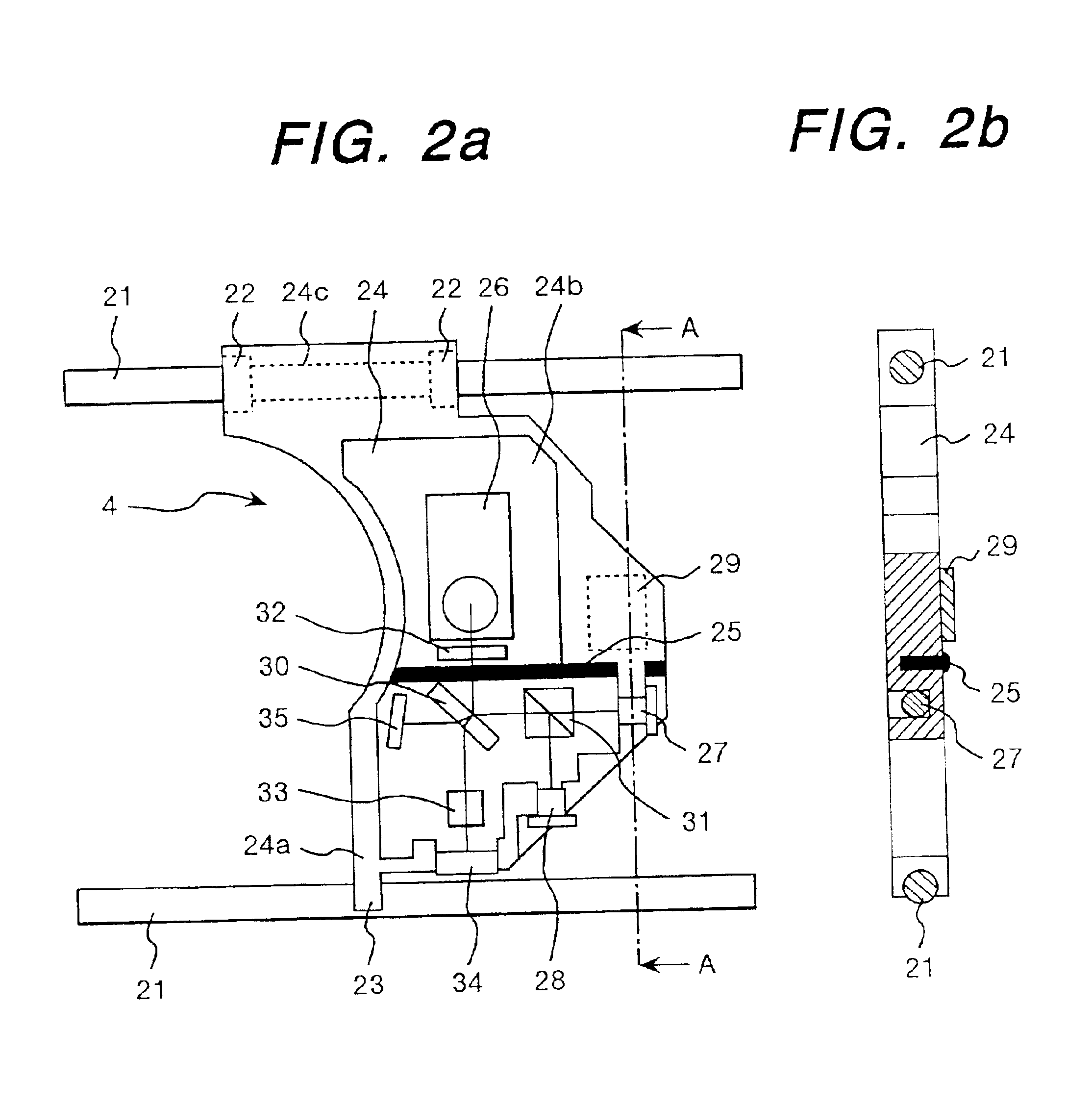
Next, a second embodiment according to the present invention will be described with reference to FIGS. 3(a), 3(b) and FIGS. 4(a) to 4(d). The FIGS. 3(a) and 3(b) show a plane view and a cross-sectional view, respectively, of an optical pickup in the disc driving apparatus according to the FIGS. 4(a) to 4(d) are diagrams illustrating the condition of flow-through within the optical pickup mentioned above. However, in this second embodiment, an explanation will be omitted of those portions duplicating elements in the first embodiment. Also, in this second embodiment, the constituent elements commonly provided in the first embodiment achieve the same effects thereof.

The function of the optical pickup 4 is to reproduce or record information on the disc 1. For this reason, in the disc driving apparatus 40 (see FIG. 1), there is provided a means for shifting or moving the optical pickup 4 to a predetermined position on the disc 1, and as a guide for it, in the side of the apparatus, for ...


PUM

PropertyMeasurementUnit
wavelengthaaaaaaaaaa
thermal conductivityaaaaaaaaaa

Abstract

In a disc driving apparatus, wherein a laser diode and a laser driver circuit board are mounted on a pickup housing in thermal contact therewith and are disposed adjacent to each other, a heat separation member is provided between the laser diode and the laser driver circuit board for effecting thermal separation therebetween, thereby reducing the thermal interference between the heat-generating elements that are adjacent to each other in the optical pickup. This makes it possible to protect the heat-generating elements from being deteriorated, leading to a reduction in the lifetime thereof, as well as, to improve the reliability thereof.

Description

BACKGROUND OF THE INVENTIONThe present invention relates to a disc driving apparatus equipped with an optical pickup for reproducing or reproducing / recording information on an optical disc; and, in particular, the invention relates to a disc driving apparatus which is suitable for as a so-called CD-ROM drive, a DVD-ROM drive, and a DVD-RAM drive, etc.A laser light generation device and an optical disc read-out / write-in apparatus equipped therewith have been described in, for example, Japanese Patent Laying-Open No. Hei 10-283650 (1998) (conventional art 1). In such a device, a thermally conductive sheet is disposed between a first heat radiation member and a second heat radiation member, wherein the area of control is increased between the first heat radiation member and the second heat radiation member, compared to the case where both members are in contact with each other directly. Thereby, radiating heat, which is generated in a heat generating element, such as a semiconductor la...

Claims


Application Information

Patent Timeline
Patent Type & Authority Patents(United States)
IPC IPC(8): G11B33/14G11B7/125G11B7/12G11B7/00G11B7/123G11B7/127
CPCG11B7/1205G11B33/1406G11B7/127G11B2007/0006G11B7/123
Inventor YAMAUCHI, YOSHIAKIKIMURA, KATSUHIKOSATAKE, MITSUOOCHI, MANABUKATO, SEIICHI
Owner HITACHI CONSUMER ELECTRONICS CORP
Why Eureka
Try Eureka