Hydraulic type brake apparatus

a technology of hydraulic brakes and brake valves, which is applied in the direction of braking systems, gearing control, couplings, etc., can solve the problems of difficult operation and difficulty in setting the set value of relief valves, and achieve the effect of increasing the opening pressure of relief valves and increasing the braking for

Inactive Publication Date: 2005-03-29
VOLVO CONSTR EQUIP
View PDF7 Cites 3 Cited by
  • Summary
  • Abstract
  • Description
  • Claims
  • Application Information

AI Technical Summary

Benefits of technology

Accordingly, it is an object of the present invention to provide a hydraulic brake apparatus in which it is possible to use a set value of a relief valve during a turning operation based on a characteristic that an opening pressure of a relief valve is increased in accordance with the size of a back pressure which is a pressure in the side of an outlet of a relief valve, and there is provided a unit for increasing the back pressure in the side of the outlet of a relief valve during the stop of the turn for thereby decreasing a turn move-back degree by increasing a braking force by increasing an opening pressure of a relief valve.

Problems solved by technology

It is difficult to adjust the set value of the relief valve for implementing a desired braking effect based on the above limit with respect to the set value of the relief valve.
In addition, an over move-back phenomenon occurs in the turn due to a lack of a braking force during a stop of turn in a construction heavy equipment which uses the turning system, so that it is difficult to operate for thereby causing a safety accident.

Method used


Image

  • Hydraulic type brake apparatus
  • Hydraulic type brake apparatus
  • Hydraulic type brake apparatus

Examples


Embodiment Construction

The preferred embodiment of the present invention will be described with reference to the accompanying drawings.

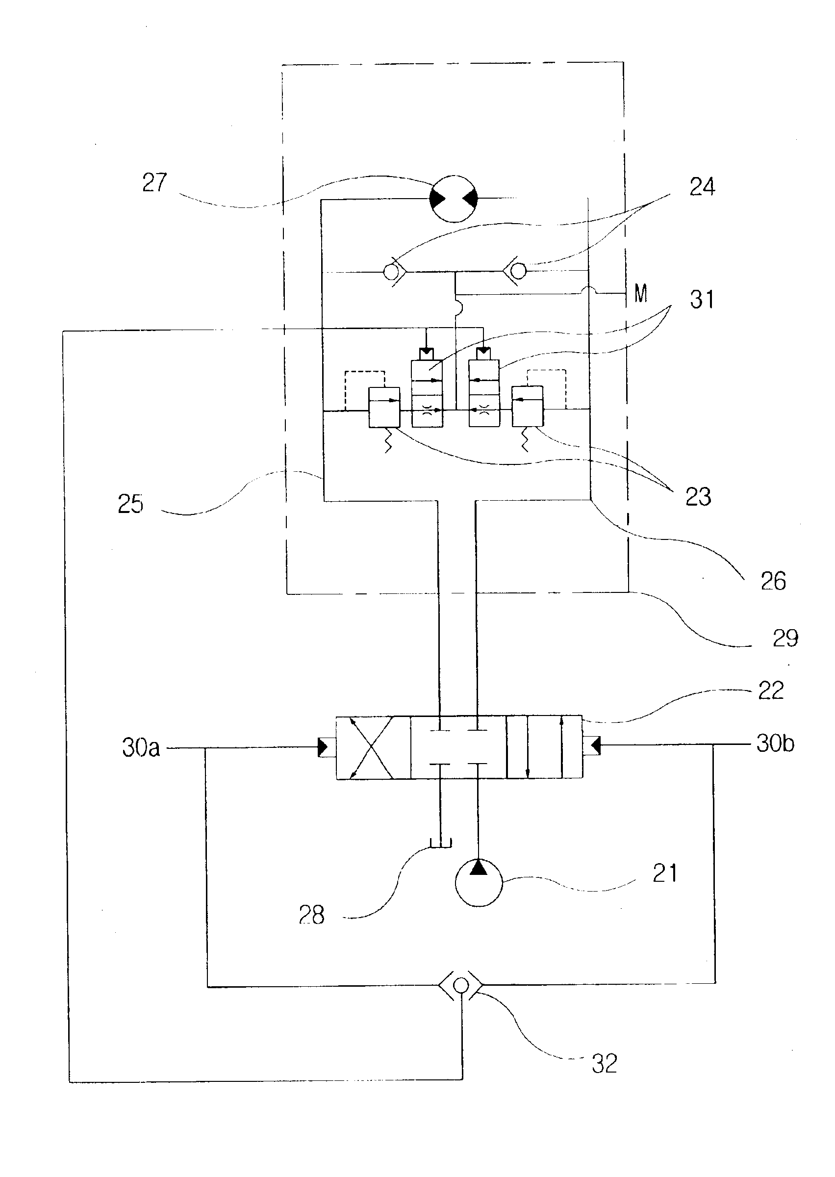
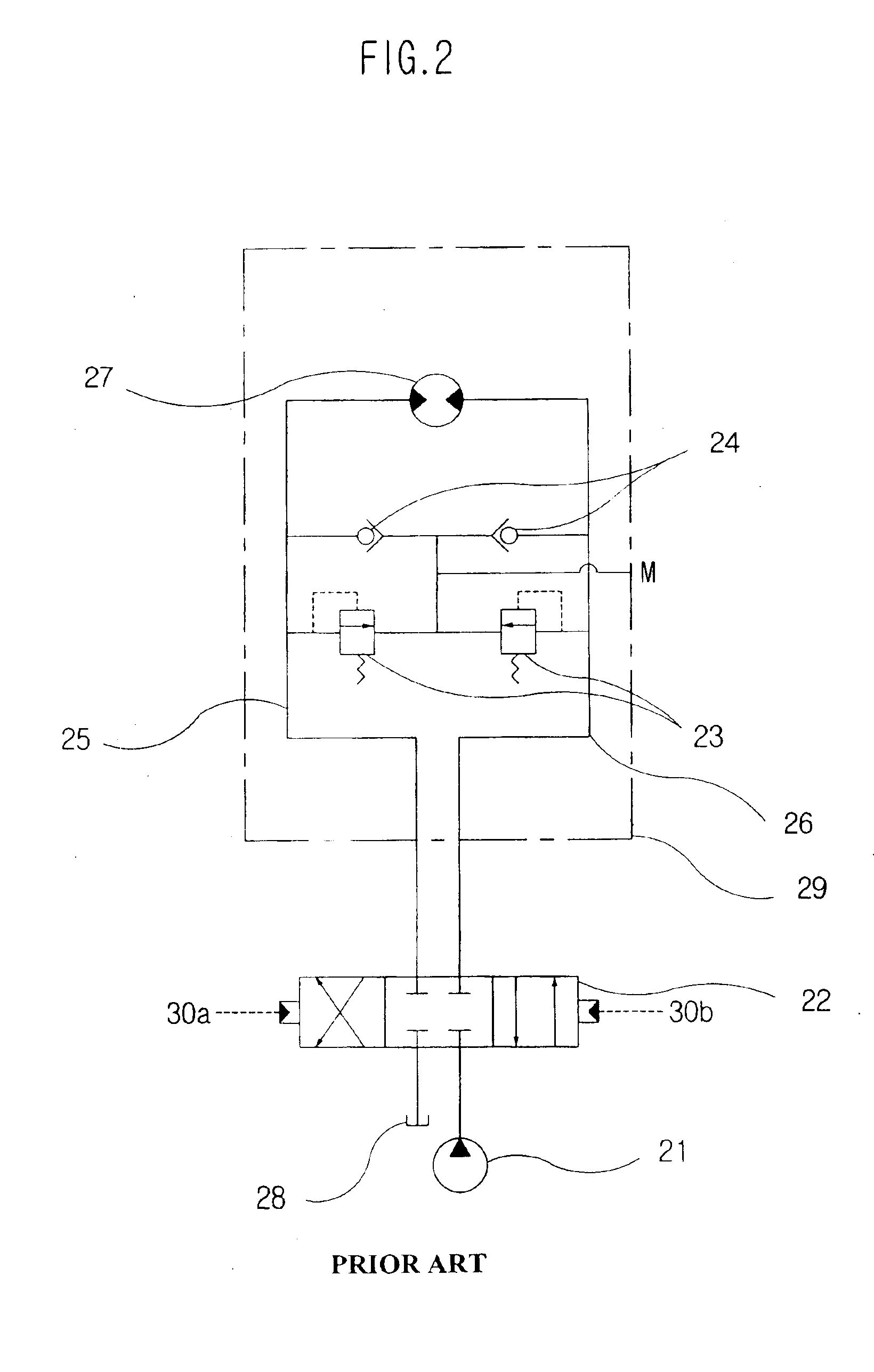
FIG. 3 is a hydraulic circuit diagram illustrating a hydraulic brake apparatus according to the present invention. As shown therein, in the conventional hydraulic brake apparatus of FIG. 2, there is further provided a switch throttling valve in a lower flow portion of a relief valve.

The description of the elements same as the conventional art will be omitted. The elements same as the conventional art will be given the same reference numerals.

In the functions of the hydraulic circuit, when the direction changing valve 22 is switched to a neutral position for stopping the hydraulic motor 27, a pilot signal pressure of the direction changing valve 22 is in parallel in a bi-directional check valve 32, and the bi-directional check valve 32 is connected with a pilot port of the switching throttling valve 31. As the directional changing valve 22 is switched to a neutral position,...


PUM


Abstract

The present invention relates to a hydraulic type brake system which includes a unit for adjusting a back pressure in a turn driving hydraulic circuit mounted in a construction heavy equipment such as an excavator, etc., and in particular to a hydraulic type brake apparatus which is used together with a relief valve installed various actuator driving hydraulic circuits for adjusting a back pressure in a lower flow side of a relief valve for thereby adjusting an opening pressure of a relief valve. There is provided a back pressure adjusting unit adapted to adjust an opening pressure of the relief valve by adjusting a back pressure of the hydraulic circuit in a lower flow portion of the relief valve based on a co-operation with the actuator.

Description

BACKGROUND OF THE INVENTION1. Field of the InventionThe present invention relates to a hydraulic type brake system which includes a unit for adjusting a back pressure in a turn driving hydraulic circuit mounted in a construction heavy equipment such as an excavator, etc., and in particular to a hydraulic type brake apparatus which is used together with a relief valve installed various actuator driving hydraulic circuits for adjusting a back pressure in a lower flow side of a relief valve for thereby adjusting an opening pressure of a relief valve.2. Description of the Background ArtA relief valve is directed to draining a part or all of a hydraulic oil in a direction of a hydraulic pressure tank for thereby maintaining a pressure of a hydraulic pressure circuit below a set value when the maximum pressure of a hydraulic circuit reaches at a set value of a valve.FIG. 1 is an inner cross-sectional view of a direct driven type relief valve which is an example of a relief valve.The relie...

Claims


Application Information

Patent Timeline
Patent Type & Authority Patents(United States)
IPC IPC(8): B60T1/00B60T1/093F15B11/044F15B11/00F15B11/08
CPCB60T1/093F16H61/4148F15B11/0445F16H61/4157F15B2211/20538F15B2211/30525F15B2211/3111F15B2211/329F15B2211/40515F15B2211/428F15B2211/45F15B2211/50527F15B2211/5154F15B2211/7058F15B2211/715B60T11/10
Inventor KIM, YEON HO
Owner VOLVO CONSTR EQUIP
Why Eureka
Try Eureka